
Supplementary Document

ADHESIVES
www.powers.com
21
TECH MANUAL – ADHESIVES ©2016 POWERS VOLUME 1 – REV. M
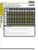
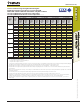
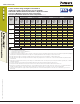
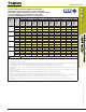
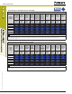
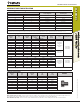
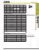
STRENGTH DESIGN (SD)
Tension and Shear Design Strength for Threaded Rod
Installed in Cracked Concrete (Bond or Concrete Strength)
Drilled with a Hammer-Drill and Carbide Bit in a Dry Hole Condition
162°F (72°C) Maximum Long-Term Service Temperature;
248°F (120°C) Maximum Short-Term Service Temperature
1,2,3,4,5,6,7,8,9
®
Nominal
Rod/Rebar
Size
(in.)
Embed.
Depth
h
ef
(in.)
Minimum Concrete Compressive Strength
f'c = 2,500 (psi) f'c = 3,000 (psi) f'c = 4,000 (psi) f'c = 6,000 (psi) f'c = 8,000 (psi)
φ
N
cb
or
φ
N
a
Tension
(lbs.)
φ
V
cb
or
φ
V
cp
Shear
(lbs.)
φ
N
cb
or
φ
N
a
Tension
(lbs.)
φ
V
cb
or
φ
V
cp
Shear
(lbs.)
φ
N
cb
or
φ
N
a
Tension
(lbs.)
φ
V
cb
or
φ
V
cp
Shear
(lbs.)
φ
N
cb
or
φ
N
a
Tension
(lbs.)
φ
V
cb
or
φ
V
cp
Shear
(lbs.)
φ
N
cb
or
φ
N
a
Tension
(lbs.)
φ
V
cb
or
φ
V
cp
Shear
(lbs.)
1/2
2-3/4 690 1,480 705 1,515 730 1,575 770 1,660 800 1,725
4 1,000 2,155 1,025 2,205 1,065 2,290 1,120 2,415 1,165 2,505
6 1,500 3,235 1,535 3,310 1,595 3,435 1,680 3,620 1,745 3,760
5/8
3-1/8 1,015 1,985 1,040 2,195 1,080 2,330 1,140 2,455 1,185 2,550
5 1,625 3,505 1,665 3,590 1,730 3,725 1,825 3,925 1,895 4,075
7-1/2 2,440 5,255 2,500 5,385 2,595 5,590 2,735 5,890 2,840 6,115
3/4
3-1/2 1,365 2,545 1,400 2,815 1,455 3,130 1,530 3,300 1,590 3,425
6 2,345 5,045 2,400 5,170 2,490 5,365 2,625 5,655 2,725 5,870
9 3,515 7,570 3,600 7,750 3,735 8,045 3,940 8,485 4,090 8,805
7/8
3-1/2 1,425 2,660 1,460 2,945 1,510 3,255 1,585 3,415 1,640 3,535
7 3,190 6,870 3,265 7,035 3,390 7,300 3,575 7,700 3,710 7,990
10-1/2 4,785 10,305 4,900 10,550 5,085 10,955 5,360 11,545 5,565 11,985
1
4 1,885 3,255 1,925 3,595 1,990 4,215 2,090 4,505 2,165 4,665
8 4,165 8,970 4,265 9,190 4,430 9,540 4,670 10,055 4,845 10,435
12 6,250 13,460 6,400 13,780 6,640 14,305 7,000 15,080 7,270 15,655
■ - Concrete Breakout Strength ■ - Bond Strength/Pryout Strength
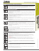
1. Tabular values are provided for illustration and are applicable for single anchors installed in uncracked normal-weight concrete with minimum slab thickness,
h
a
= h
min
, and with the following conditions:
- c
a1
is greater than or equal to the critical edge distance, c
ac
- c
a2
is greater than or equal to 1.5 times c
a1
.
2. Calculations were performed according to ACI 318-14 Ch.17 and ICC-ES AC308. The load level corresponding to the failure mode listed [Concrete breakout strength, bond strength/pryout
strength] must be checked against the tabulated steel strength of the corresponding threaded rod or rebar size and type, the lowest load level controls.
3. Strength reduction factors (
φ
) for concrete breakout strength are based on ACI 318-14 Section 5.3 for load combinations. Condition B was assumed.
4. Strength reduction factors (
φ
) for bond strength are determined from reliability testing and qualification in accordance with ICC-ES AC308 and are tabulated in this product information
and in ESR-2582.
5. Tabular values are permitted for static loads only, seismic loading is not considered with these tables. Periodic special inspection must be performed where required by code, see ESR-2582
for applicable information.
6. For anchors subjected to tension resulting from sustained loading a supplemental check must be performed according to ACI 318-14 17.3.1.2.
7. For designs that include combined tension and shear, the interaction of tension and shear loads must be calculated in accordance with ACI 318-14 Ch.17.
8. Interpolation is not permitted to be used with the tabular values. For intermediate base material compressive strengths, please see ACI 318-14 Ch.17, ICC-ES AC308 and information
included in this product supplement. For other design conditions including seismic considerations please see ACI 318-14 Ch.17 and ICC-ES AC308 and ESR-2582.
9. Long term concrete temperatures are roughly constant over significant periods of time. Short-term elevated temperatures are those that occur over brief intervals, e.g. as a result of
diurnal cycling.