
Supplementary Document

ADHESIVES
www.powers.com
15
TECH MANUAL – ADHESIVES ©2016 POWERS VOLUME 1 – REV. M
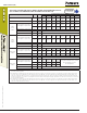
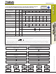
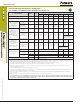
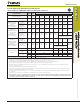
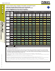
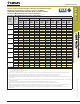
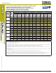
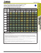
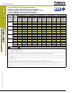
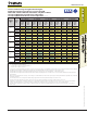
STRENGTH DESIGN (SD)
Tension and Shear Design Strength for Threaded Rod and Reinforcing Bar
Installed in Uncracked Concrete (Bond or Concrete Strength)
Drilled with a Hammer-Drill and Carbide Bit in a Dry Hole Condition
75°F (24°C) Maximum Long-Term Service Temperature;
104°F (40°C) Maximum Short-Term Service Temperature
1,2,3,4,5,6,7,8
Nominal
Rod/Rebar
Size
(in. or #)
Embed.
Depth
h
ef
(in.)
Minimum Concrete Compressive Strength
f'c = 2,500 (psi) f'c = 3,000 (psi) f'c = 4,000 (psi) f'c = 6,000 (psi) f'c = 8,000 (psi)
φ
N
cb
or
φ
N
a
Tension
(lbs.)
φ
V
cb
or
φ
V
cp
Shear
(lbs.)
φ
N
cb
or
φ
N
a
Tension
(lbs.)
φ
V
cb
or
φ
V
cp
Shear
(lbs.)
φ
N
cb
or
φ
N
a
Tension
(lbs.)
φ
V
cb
or
φ
V
cp
Shear
(lbs.)
φ
N
cb
or
φ
N
a
Tension
(lbs.)
φ
V
cb
or
φ
V
cp
Shear
(lbs.)
φ
N
cb
or
φ
N
a
Tension
(lbs.)
φ
V
cb
or
φ
V
cp
Shear
(lbs.)
3/8 or #3
2-3/8 2,635 2,490 2,700 2,755 2,805 3,020 2,955 3,180 3,070 3,305
3 3,330 3,705 3,410 4,100 3,540 4,805 3,735 6,010 3,875 7,045
4-1/2 4,995 6,765 5,115 7,480 5,310 8,770 5,600 10,965 5,810 12,520
1/2 or #4
2-3/4 3,555 3,305 3,895 3,755 4,330 4,520 4,560 5,655 4,735 6,625
4 5,920 6,560 6,065 7,255 6,295 8,505 6,635 10,635 6,890 12,470
6 8,885 11,950 9,095 13,215 9,445 15,490 9,955 19,380 10,335 22,255
5/8 or #5
3-1/8 4,310 4,120 4,720 4,680 5,450 5,720 6,400 7,510 6,625 8,805
5 8,720 9,985 9,475 11,310 9,835 13,255 10,370 16,580 10,765 19,430
7-1/2 13,880 18,625 14,210 20,595 14,755 24,140 15,550 30,195 16,145 34,775
3/4 or #6
3-1/2 5,105 5,015 5,595 5,700 6,460 6,970 7,805 9,255 8,315 11,275
6 11,465 13,595 12,560 15,445 14,165 18,715 14,930 23,410 15,500 27,440
9 19,985 26,300 20,465 29,085 21,245 34,090 22,395 42,640 23,250 49,980
7/8 or #7
3-1/2 5,105 4,930 5,595 5,605 6,460 6,855 7,725 9,100 8,225 11,130
7 14,445 16,605 15,825 18,865 18,275 23,075 20,320 29,490 21,095 34,565
10-1/2 26,540 32,800 27,855 36,635 28,920 42,940 30,485 53,710 31,645 62,955
1 or #8
4 6,240 6,115 6,835 6,945 7,895 8,495 9,255 11,280 9,850 13,800
8 17,650 19,750 19,335 22,435 22,325 27,440 23,890 34,530 24,800 40,475
12 31,980 38,790 32,745 42,900 33,995 50,280 35,835 62,895 37,200 73,720
#9
5 7,445 7,110 8,155 8,080 9,420 9,880 10,535 13,125 11,220 16,055
10 21,060 23,055 23,070 26,190 25,495 31,480 26,875 39,375 27,900 46,150
15 35,975 44,235 36,840 48,920 38,240 57,335 40,310 71,720 41,850 84,065
1-1/4
5 8,720 8,170 9,555 9,285 10,990 11,355 12,015 15,085 12,740 18,300
10 24,665 26,380 26,920 29,930 27,950 35,080 29,460 43,880 30,585 51,435
15 39,435 49,290 40,385 54,510 41,920 63,895 44,190 79,920 45,875 93,675
#10
5 8,720 8,160 9,555 9,270 10,865 11,335 11,875 15,060 12,585 18,270
10 24,665 26,430 26,920 29,985 27,950 35,145 29,460 43,960 30,585 51,525
15 39,435 49,385 40,385 54,610 41,920 64,010 44,190 80,070 45,875 93,850
■ - Concrete Breakout Strength ■ - Bond Strength/Pryout Strength
1. Tabular values are provided for illustration and are applicable for single anchors installed in uncracked normal-weight concrete with minimum slab thickness,
h
a
= h
min
, and with the following conditions:
- c
a1
is greater than or equal to the critical edge distance, c
ac
- c
a2
is greater than or equal to 1.5 times c
a1
.
2. Calculations were performed following methodology in ACI 318-14, Ch.17 and ICC-ES AC308. The load level corresponding to the failure mode listed [Concrete breakout strength,
bond strength/pryout strength] must be checked against the tabulated steel strength of the corresponding threaded rod or rebar size and type, the lowest load level controls. This
temperature range is not recognized by ACI 318-14 or ACI 318-11 and does not meet the minimum temperature requirements from ACI 355.4 Table 8.1 and
consequently is not applicable to design under ACI 318-14, ACI 318-11 or current and past editions of the international building code (IBC). The tabulated values
are provided for analysis and evaluation of existing conditions only.
3. Strength reduction factors (
φ
) for concrete breakout strength are based on ACI 318-14 Section 5.3 for load combinations. Condition B was assumed.
4. Strength reduction factors (
φ
) for bond strength are determined from reliability testing and qualification in accordance with ICC-ES AC308 and are tabulated in this product information
and in ESR-2582.
5. Tabular values are permitted for short-term static loads only, seismic loading is not considered with these tables.
6. For designs that include combined tension and shear, the interaction of tension and shear loads must be calculated in accordance with ACI 318-14, Ch.17.
7. Interpolation is not permitted to be used with the tabular values. For intermediate base material compressive strengths, please see ACI 318-14, Ch.17, ICC-ES AC308 and information
included in this product supplement. For other design conditions including seismic considerations please see ACI 318-14, Ch.17 and ICC-ES AC308 and ESR-2582.
8. Long term concrete temperatures are roughly constant over significant periods of time. Short-term elevated temperatures are those that occur over brief intervals, e.g. as a result of
diurnal cycling.