
pdf-doc

www.powers.com
9
aDhesiVe anchors
STRENGTH DESIGN (SD)
TECH MANUAL – ADHESIVE ANCHORS ©2015 POWERS VOLUME 1 – 9/2015 – REV. G
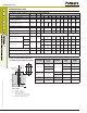
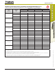
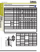
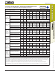
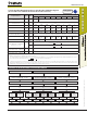
Concrete Breakout Design Information for Threaded Rod and Reinforcing Bars
(For use with loads combinations taken from ACI 318 Section 9.2)
1
Code listed
ICC-ES ESR-2583
Design Information Symbol Units
Nominal Rod Diameter (inch) / Reinforcing Bar Size
3/8 or #3 1/2 or #4 5/8 or #5 3/4 or #6 7/8 or #7 1 or #8 #9
1-1/4 or
#10
Effectiveness factor for
cracked concrete
k
c,cr
-
(SI)
Not
Applicable
17
(7.1)
Effectiveness factor for
uncracked concrete
k
c,uncr
-
(SI)
24
(10.0)
Minimum embedment h
ef,min
inch
(mm)
2-3/8
(60)
2-3/4
(70)
3-1/8
(79)
3-1/2
(89)
3-1/2
(89)
4
(102)
4-1/2
(114)
5
(127)
Maximum embedment h
ef,max
inch
(mm)
7-1/2
(191)
10
(254)
12-1/2
(318)
15
(381)
17-1/2
(445)
20
(508)
22-1/2
(572)
25
(635)
Minimum anchor spacing s
min
inch
(mm)
1-7/8
(48)
2-1/2
(64)
3-1/8
(79)
3-3/4
(95)
4-3/8
(111)
5
(127)
5-5/8
(143)
6-1/4
(159)
Minimum edge distance
2
c
min
inch
(mm)
5
d
where
d
is nominal outside diameter of the anchor
Minimum edge distance,reduced
2
c
min,red
inch
(mm)
1-3/4
(45)
1-3/4
(45)
1-3/4
(45)
1-3/4
(45)
1-3/4
(45)
1-3/4
(45)
2-3/4
(70)
2-3/4
(70)
Minimum member thickness h
min
inch
(mm)
h
ef
+ 1-1/4
(h
ef
+ 30)
h
ef
+ 2d
o
where d
o
is hole diameter;
Critical edge distance—splitting (for
uncracked concrete only)
3
c
ac
inch
c
ac
= h
ef
(
t
uncr
1160
)
0.4
[3.1-0.7
h
h
ef
]
(mm)
c
ac
= h
ef
(
t
uncr
8
)
0.4
[3.1-0.7
h
h
ef
]
Strength reduction factor for tension,
concrete failure modes, Condition B
4
f
- 0.65
Strength reduction factor for shear,
concrete failure modes, Condition B
4
f
- 0.70
For SI: 1 inch = 25.4 mm, 1 lbf = 4.448 N. For pound-inch units: 1 mm = 0.03937 inch, 1 N = 0.2248 lbf.
1. Additional setting information is described in the installation instructions.
2. For installation between the minimum edge distance, c
min
, and the reduced minimum edge distance, c
min,red
, the maximum torque applied must be reduced (multiplied) by a factor of 0.45.
3.
t
k,uncr
need not be taken as greater than:
t
k,uncr =
√
h
ef
• f'c
k
uncr
•
π
• d
and
h
h
ef
need not be taken as larger than 2.4.
4. Condition A requires supplemental reinforcement, while Condition B applies where supplemental reinforcement is not provided or where pryout governs, as set forth in ACI 318 D.4.3. The
tabulated value of
f
applies when the load combinations of Section 1605.2 of the IBC or ACI 318 Section 9.2 are used in accordance with ACI 318 D.4.4. If the load combinations of ACI
318 Appendix C are used, the appropriate value of
f
must be determined in accordance with ACI 318 D.4.4.
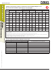
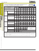
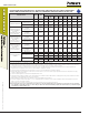
fLoWCHArT for THE ESTABLISHMEnT of DESIGn BonD STrEnGTH
Cracked Concrete
Normal or Lightweight Concrete
Dry
Concrete
Water
Saturated
Concrete
Water-Filled
Hole
(Flooded)
Hammer-Drill
f’c
t
k,cr
t
k,cr •
κ
ws
t
k,cr •
κ
wf
f
d
f
ws
f
wf
Uncracked Concrete
Normal or Lightweight Concrete
Dry
Concrete
Water
Saturated
Concrete
Water-Filled
Hole
(Flooded)
Hammer-Drill
f’c
t
k,uncr
t
k,uncr •
κ
ws
t
k,uncr •
κ
wf
f
d
f
ws
f
wf
Normal or Lightweight Concrete
Dry
Concrete
Water
Saturated
Concrete
Water-Filled
Hole
(Flooded)
Core Drill
f’c
t
k,uncr
t
k,uncr •
κ
ws
t
k,uncr •
κ
wf
f
d
f
ws
f
wf