
pdf-doc

aDhesiVe anchors
www.powers.com
8
TECH MANUAL – ADHESIVE ANCHORS ©2015 POWERS VOLUME 1 – 9/2015 – REV. G
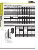
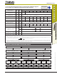
STRENGTH DESIGN (SD)
Steel Tension and Shear Design for Reinforcing Bars in Normal Weight Concrete
(For use with load combinations taken from ACI318 Section 9.2)
Code listed
ICC-ES ESR-2583
Design Information Symbol Units
Nominal Reinforcing Bar Size (Rebar)
1
No. 3 No. 4 No. 5 No. 6 No. 7 No. 8 No. 9 No. 10
Rebar nominal outside diameter d
inch
(mm)
0.375
(9.5)
0.500
(12.7)
0.625
(15.9)
0.750
(19.1)
0.875
(22.2)
1.000
(25.4)
1.125
(28.7)
1.250
(32.3)
Rebar effective cross-sectional area A
se
inch
2
(mm
2
)
0.110
(71.0)
0.200
(129.0)
0.310
(200.0)
0.440
(283.9)
0.600
(387.1)
0.790
(509.7)
1.000
(645.2)
1.270
(819.4)
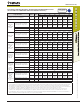
ASTM
A 615
Grade 75
Nominal strength as governed by
steel strength (for a single anchor)
N
sa
lbf
(kN)
11,000
(48.9)
20,000
(89.0)
31,000
(137.9)
44,000
(195.7)
60,000
(266.9)
79,000
(351.4)
100,000
(444.8)
127,000
(564.9)
V
sa
lbf
(kN)
6,600
(29.4)
12,000
(53.4)
18,600
(82.7)
26,400
(117.4)
36,000
(160.1)
47,400
(210.8)
60,000
(266.9)
76,200
(338.9)
Reduction factor for seismic shear
a
V,seis
- 0.70 0.70 0.80 0.80 0.80 0.80 0.80 0.80
Strength reduction factor for tension
3
f
- 0.65
Strength reduction factor for shear
3
f
- 0.60
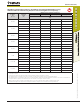
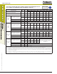
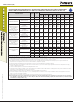
ASTM
A 615
Grade 60
Nominal strength as governed by
steel strength (for a single anchor)
N
sa
lbf
(kN)
9,900
(44.0)
18,000
(80.1)
27,900
(124.1)
39,600
(176.1)
54,000
(240.2)
71,100
(316.3)
90,000
(400.3)
114,300
(508.4)
V
sa
lbf
(kN)
5,940
(26.4)
10,800
(48.0)
16,740
(74.5)
23,760
(105.7)
32,400
(144.1)
42,660
(189.8)
54,000
(240.2)
68,580
(305.0)
Reduction factor for seismic shear
a
V,seis
- 0.70 0.70 0.80 0.80 0.80 0.80 0.80 0.80
Strength reduction factor for tension
2
f
- 0.75
Strength reduction factor for shear
2
f
- 0.65
ASTM A 706
Grade 60
Nominal strength as governed by
steel strength (for a single anchor)
N
sa
lbf
(kN)
8,800
(39.1)
16,000
(71.2)
24,800
(110.3)
35,200
(156.6)
48,000
(213.5)
63,200
(281.1)
80,000
(355.9)
101,600
(452.0)
V
sa
lbf
(kN)
5,280
(23.5)
9,600
(42.7)
14,880
(66.2)
21,120
(94.0)
28,800
(128.1)
37,920
(168.7)
48,000
(213.5)
60,960
(271.2)
Reduction factor for seismic shear
a
V,seis
- 0.70 0.70 0.80 0.80 0.80 0.80 0.80 0.80
Strength reduction factor for tension
2
f
- 0.75
Strength reduction factor for shear
2
f
- 0.65
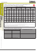
ASTM A 615
Grade 40
Nominal strength as governed by
steel strength (for a single anchor)
N
sa
lbf
(kN)
6,600
(29.4)
12,000
(53.4)
18,600
(82.7)
26,400
(117.4)
In accordance with ASTM A 615, Grade
40 bars are furnished only in sizes No. 3
through No. 6
V
sa
lbf
(kN)
3,960
(17.6)
7,200
(32.0)
11,160
(49.6)
15,840
(70.5)
Reduction factor for seismic shear
a
V,seis
- 0.70 0.70 0.80 0.80
Strength reduction factor for tension
2
f
- 0.75
Strength reduction factor for shear
2
f
- 0.65
For SI: 1 inch = 25.4 mm, 1 lbf = 4.448 N. For pound-inch units: 1 mm = 0.03937 inches, 1 N = 0.2248 lbf.
1. Values provided for reinforcing bar material types based on minimum specified strengths and calculated in accordance with ACI 318-11 Eq. (D-2) and Eq. (D-29).
2. The tabulated value of
f
applies when the load combinations of Section 1605.2 of the IBC or ACI 318 Section 9.2 are used in accordance with ACI 318 D.4.3. If the load combinations of
ACI 318 Appendix C are used, the appropriate value of
f
must be determined in accordance with ACI 318 D.4.4. Values correspond to ductile steel elements. In accordance with ACI 318
D.3.3.4.3(a)6, deformed reinforcing bar meeting this specification used as ductile steel elements to resist earthquake effects shall be limited to reinforcing bars satisfying the requirements
of ACI 318 section 21.1.5.2(a) and (b).
3. The tabulated value of
f
applies when the load combinations of Section 1605.2 of the IBC or ACI 318 Section 9.2 are used in accordance with ACI 318 D.4.3. If the load combinations of
ACI 318 Appendix C are used, the appropriate value of
f
must be determined in accordance with ACI 318 D.4.4. Values correspond to brittle steel elements.