
pdf-doc

aDhesiVe anchors
www.powers.com
6
TECH MANUAL – ADHESIVE ANCHORS ©2015 POWERS VOLUME 1 – 9/2015 – REV. G
STRENGTH DESIGN (SD)
STRENGTH DESIGN (SD)
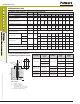
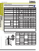
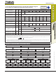
Installation Specifications for Threaded Rod and Reinforcing Bar
1
Code listed
ICC-ES ESR-2583
Dimension/Property Notation Units Nominal Anchor Size
Threaded Rod - - 3/8" 1/2" - 5/8" 3/4" 7/8" 1" - 1-1/4" -
Reinforcing Bar - - #3 - #4 #5 #6 #7 #8 #9 - #10
Nominal anchor diameter d
in.
(mm)
0.375
(9.5)
0.500
(12.7)
0.625
(15.9)
0.750
(19.1)
0.875
(22.2)
1.000
(25.4)
1.125
(28.6)
1.250
(31.8)
1.250
(31.8)
Carbide drill bit nominal size d
o
[d
bit
] in.
7/16
ANSI
9/16
ANSI
5/8
ANSI
11/16
or 3/4
ANSI
7/8
ANSI
1
ANSI
1-1/8
ANSI
1-3/8
ANSI
1-3/8
ANSI
1-1/2
ANSI
Diamond core bit nominal size d
o
[d
bit
] in. - 5/8 3/4 7/8 1 1-1/8 - - -
Minimum embedment h
ef,min
in.
(mm)
2-3/8
(61)
2-3/4
(70)
3-1/8
(79)
3-1/2
(89)
3-1/2
(89)
4
(102)
4-1/2
(114)
5
(127)
5
(127)
Maximum embedment
4
h
ef,max
in.
(mm)
4-1/2
(114)
10
(254)
12-1/2
(318)
15
(381)
17-1/2
(445)
20
(508)
22-1/2
(572)
25
(635)
25
(635)
Minimum concrete member thickness h
min
in.
(mm)
h
ef
+ 1-1/4
(h
ef
+ 30)
h
ef
+ 2d
o
Minimum spacing distance s
min
in.
(mm)
1-7/8
(48)
2-1/2
(62)
3-1/8
(80)
3-3/4
(95)
4-3/8
(111)
5
(127)
5-5/8
(143)
6-1/4
(159)
6-1/4
(159)
Minimum edge distance c
min
in.
(mm)
1-3/4
(45)
2-3/4
(70)
Maximum torque
2
For c ≥ 5d
T
inst
ft.-lbf.
(N-m)
15
(20)
33
(44)
60
(81)
105
(142)
125
(169)
165
(223)
-
280
(379)
-
For c < 5d
7
(9)
15
(20)
27
(36)
47
(63)
56
(75)
74
(100)
-
126
(170)
-
Maximum torque
2,3
For c ≥ 5d
T
inst
ft.-lbf.
(N-m)
10
(13)
25
(33)
50
(67)
90
(122)
125
(169)
165
(223)
-
280
(379)
-
For c < 5d
5
(6)
11
(14)
22
(29)
40
(54)
56
(75)
74
(100)
-
126
(170)
-
Effective cross sectional area of threaded rod A
se
in.
2
(mm
2
)
0.078
(50)
0.142
(92)
0.226
(146)
0.335
(216)
0.462
(298)
0.606
(391)
-
0.969
(625)
-
Effective cross sectional area of reinforcing bar A
se
in.
2
(mm
2
)
0.110
(71)
0.200
(129)
0.310
(200)
0.440
(284)
0.600
(387)
0.790
(510)
1.000
(645)
-
1.270
(819)
For SI: 1 inch = 25.4 mm, 1 ft-lbf = 1.356 N-m. For pound-inch units: 1 mm = 0.03937 inch, 1 N-m = 0.7375 ft-lbf.
1. For use with the design provisions of ACI 318 Appendix D, ICC-ES AC308 Section 4.2 and ESR-2583
2. Torque may not be applied to the anchors until the full cure time of the adhesive has been achieved
3. These torque values apply to ASTM A36/F 1554 Grade 36 threaded rods
4. The maximum embedment is limited to 12 diameters for the horizontal and upwardly inclined installations and for installations in water-filled (flooded) holes with a carbide drill bit.
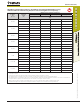
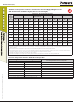
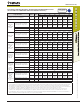
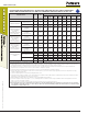
Detail of Steel Hardware Elements
used with Injection Adhesive System
Steel Description
(General)
Steel
Specification
(ASTM)
Nominal Anchor
Size (inch)
Minimum
Yield
Strength
f
y
(ksi)
Minimum
Ultimate
Strength
f
u
(ksi)
Carbon Rod
A 36 or F 1554,
Grade 36
3/8 through 1-1/4
36.0 58.0
F 1554 Grade 55 55.0 75.0
A 193, Grade B7 or
F 1554, Grade 105
105.0 125.0
Stainless Rod
(Alloy 304 / 316)
F 593
Condition CW
3/8 through 5/8 65.0 100.0
3/4 through 1-1/4 45.0 85.0
Grade 60
Reinforcing Bar
A 615, or
A 767, A 996
3/8 through 1-1/4
(#3 through #10)
60.0 90.0
A 706 60.0 80.0
Grade 40
Reinforcing Bar
A 615
3/8 through 3/4
(#3 through #6)
40.0 60.0
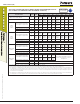
T
max
h
ef
h
c
c
s
d
d
o
(d
bit
)
Threaded Rod
or Rebar