
pdf-doc

www.powers.com
5
aDhesiVe anchors
REFERENCE DATA (ASD)
TECH MANUAL – ADHESIVE ANCHORS ©2015 POWERS VOLUME 1 – 9/2015 – REV. G
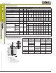
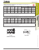
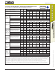
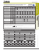
Ultimate Load Capacities for Threaded Rod Installed with PE1000+ into the Block Face of
Grout-Filled Concrete Masonry Walls
1,2
Nominal
Rod
Diameter
d.
in.
Drill
Diameter
d
bit
in.
Minimum
Embedment
Depth
in.
(mm)
Minimum
Edge
Distance
in.
(mm)
Minimum
End
Distance
in.
(mm)
Ultimate Load
3
Allowable Load
Tension
lbs.
(kN)
Shear
lbs.
(kN)
Tension
lbs.
(kN)
Shear
lbs.
(kN)
3/8 7/16
3
(76.2)
2-1/2
(63.5)
2-1/2
(63.5)
3,350
(14.9)
2,100
(9.3)
670
(2.9)
420
(1.9)
1/2 9/16
4
(101.6)
3
(76.2)
3
(76.2)
4,575
(20.3)
2,550
(11.3)
915
(4.1)
510
(2.3)
5/8 11/16
5
(127.0)
3-3/4
(95.3)
4
(101.6)
6,900
(30.7)
5,275
(23.5)
1,380
(6.1)
1,055
(4.7)
1. Tabulated load values are for anchors installed in minimum 8" wide, minimum Grade N, Type ll, lightweight, medium-weight or normal-weight concrete masonry units conforming to
ASTM C 90 that have reached a designated minimum compressive strength at the time of installation (f'm ≥1,500 psi). Mortar must be type N, S or M.
2. Anchor installations are limited to one per masonry cell. Shear loads may be applied in any direction.
3. The values listed are ultimate load capacities which should be reduced by a minimum safety factor of 5.0 or greater to determine the allowable working load. Consideration of safety
factors of 10 or higher may be necessary depending on the application, such as life safety.
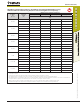
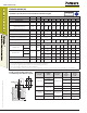
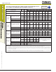
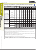
Load Capacities for Threaded Rod Installed with PE1000+ in the Top of Grout-Filled Concrete Masonry Walls
1,2
Nominal
Rod
Diameter
d.
in.
Drill
Diameter
d
bit
in.
Minimum
Embedment
Depth
in.
(mm)
Minimum
Edge
Distance
in.
(mm)
Minimum
End
Distance
in.
(mm)
Ultimate Load
3
Allowable Load
Tension
lbs.
(kN)
Shear
lbs.
(kN)
Tension
lbs.
(kN)
Shear
lbs.
(kN)
1/2 9/16
6
(152.4)
1-3/4
(44.5)
3
(76.2)
5,950
(26.4)
1,450
(6.5)
1,190
(5.3)
290
(1.3)
5/8 11/16
8
(203.2)
1-3/4
(44.5)
4
(101.6)
9,450
(42.0)
1,700
(7.5)
1,890
(8.4)
340
(1.4)
1. Tabulated load values are for anchors installed in a minimum Grade N, Type ll, lightweight, medium-weight or normal-weight masonry units conforming to ASTM C 90 that have reached
a designated minimum compressive strength at the time of installation (f'm ≥1,500 psi). Mortar must be type N, S or M.
2. Anchor installations are limited to one per masonry cell. Shear loads may be applied in any direction.
3. The values listed are ultimate load capacities which should be reduced by a minimum safety factor of 5.0 or greater to determine the allowable working load. Consideration of safety
factors of 10 or higher may be necessary depending on the application, such as life safety.
Minimum End
Distance (Typ)
Minimum
Edge Distance
(Typ)
Face Shell
Permissible Anchor Locations
(Un-hatched Area / Through Face Shell)
Grout Filled
CMU (Typ)
Top of Wall
Minimum End
Distance (Typ)
Minimum Edge
Distance (Typ)