
pdf-doc

aDhesiVe anchors
www.powers.com
4
TECH MANUAL – ADHESIVE ANCHORS ©2015 POWERS VOLUME 1 – 9/2015 – REV. G
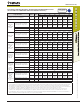
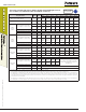
REFERENCE DATA (ASD)
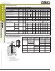
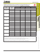
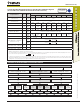
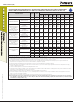
Allowable Load Capacities for PE1000+ Installed into Uncracked Normal-Weight Concrete
with Threaded Rod and Reinforcing Bar (Based on Steel Strength)
1,2,3,4,5,6
Nominal
Rod
Diameter
or Rebar
Size
(in. or #)
Steel Elements - Threaded Rod and Reinforcing Bar
A36 or F1554, Grade 36 F1554, Grade 55
A 193, Grade B7 or
F1554, Grade 105
F 593, CW (SS) Grade 60 Rebar Grade 40 Rebar
Tension
lbs
(kN)
Shear
lbs
(kN)
Tension
lbs
(kN)
Shear
lbs
(kN)
Tension
lbs
(kN)
Shear
lbs
(kN)
Tension
lbs
(kN)
Shear
lbs
(kN)
Tension
lbs
(kN)
Shear
lbs
(kN)
Tension
lbs
(kN)
Shear
lbs
(kN)
3/8 or #3
2,115
(9.4)
1,090
(4.8)
2,735
(12.2)
1,410
(6.3)
4,555
(20.3)
2,345
(10.4)
3,645
(16.2)
1,880
(8.4)
3,280
(14.6)
1,690
(7.5)
2,185
(9.7)
1,125
(5.0)
1/2 or #4
3,760
(16.7)
1,935
(8.6)
4,860
(21.6)
2,505
(11.1)
8,100
(36.0)
4,170
(18.5)
6,480
(28.8)
3,340
(14.9)
5,830
(25.9)
3,005
(13.4)
3,890
(17.3)
2,005
(8.9)
5/8 or #5
5,870
(26.1)
3,025
(13.5)
7,595
(33.8)
3,910
(17.4)
12,655
(56.3)
6,520
(29.0)
10,125
(45.0)
5,215
(23.2)
9,110
(40.5)
4,695
(20.9)
6,075
(27.0)
3,130
(13.9)
3/4 or #6
8,455
(37.6)
4,355
(19.4)
10,935
(48.6)
5,635
(25.1)
18,225
(81.1)
9,390
(41.8)
12,390
(55.1)
6,385
(28.4)
13,120
(58.4)
6,760
(30.1)
8,745
(38.9)
4,505
(20.0)
7/8 or #7
11,510
(51.2)
5,930
(26.4)
14,885
(66.2)
7,665
(34.1)
24,805
(110.3)
12,780
(56.8)
16,865
(75.0)
8,690
(38.7)
17,860
(79.4)
9,200
(40.9)
11,905
(53.0)
6,135
(27.3)
1 or #8
15,035
(66.9)
7,745
(34.5)
19,440
(86.5)
10,015
(44.5)
32,400
(144.1)
16,690
(74.2)
22,030
(98.0)
11,350
(50.5)
23,325
(103.8)
12,015
(53.4)
15,550
(69.2)
8,010
(35.6)
#9
29,680
(132.0)
15,290
(68.0)
19,785
(88.0)
10,195
(45.3)
1-1/4
23,490
(104.5)
12,100
(53.8)
30,375
(135.1)
15,645
(69.6)
50,620
(225.2)
26,080
(116.0)
34,425
(153.1)
17,735
(78.9)
#10
37,625
(167.4)
19,380
(86.2)
25,080
(111.6)
12,920
(57.5)
1. AISC defined steel strength (ASD): Tensile = 0.33 • F
u
• A
nom
, Shear = 0.17 • F
u
• A
nom
2. Allowable load capacities listed are calculated for the steel element type. Consideration of applying additional safety factors may be necessary depending on the application, such as life
safety or overhead.
3. The tabulated load values are applicable to single anchors at critical edge and spacing distances and at the minimum member thickness.
4. The tabulated load values are for dry concrete. Holes must be drilled with a hammer drill and an ANSI carbide drill bit. Installation in wet concrete or installations in water-filled holes
may require a reduction in capacity. Contact Powers Fasteners for more information concerning these installation conditions.
5. Allowable shear capacity is controlled by steel strength for the given conditions.
6. Allowable bond strength/concrete capacity must be checked against allowable steel strength in tension to determine the controlling allowable load.
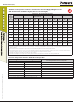
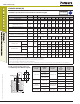
In-Service Temperature Chart for Allowable Load Capacities
1
Base Material Temperature
Bond Strength Reduction Factor for Temperature
o
F
o
C
41 5 1.00
50 10 1.00
68 20 1.00
75 14 1.00
104 40 0.85
110 43 0.82
122 50 0.76
140 60 0.69
1. Linear interpolation may be used to derive reduction factors between those listed.