
pdf-doc

aDhesiVe anchors
www.powers.com
18
TECH MANUAL – ADHESIVE ANCHORS ©2015 POWERS VOLUME 1 – 9/2015 – REV. G
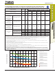
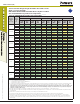
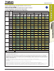
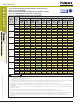
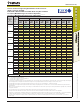
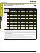
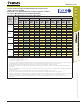
STRENGTH DESIGN (SD)
Tension and Shear Design Strength Installed in Uncracked Concrete
(Bond or Concrete Strength)
Drilled with a Core-Drill and Diamond Core Bit in a Dry Hole Condition
75°F (24°C) Maximum Long-Term Service Temperature;
104°F (40°C) Maximum Short-Term Service Temperature
1,2,3,4,5,6,7,8
Nominal
Rod/Rebar
Size
(in. or #)
Embed.
Depth
h
ef
(in.)
Minimum Concrete Compressive Strength
f'c = 2,500 psi f'c = 3,000 psi f'c = 4,000 psi f'c = 6,000 psi f'c = 8,000 psi
Φ
Ncb
or
Φ
Na
Tension
(lbs.)
Φ
Vcb or
Φ
Vcp
Shear
(lbs.)
Φ
Ncb
or
Φ
Na
Tension
(lbs.)
Φ
Vcb or
Φ
Vcp
Shear
(lbs.)
Φ
Ncb
or
Φ
Na
Tension
(lbs.)
Φ
Vcb or
Φ
Vcp
Shear
(lbs.)
Φ
Ncb
or
Φ
Na
Tension
(lbs.)
Φ
Vcb or
Φ
Vcp
Shear
(lbs.)
Φ
Ncb
or
Φ
Na
Tension
(lbs.)
Φ
Vcb or
Φ
Vcp
Shear
(lbs.)
1/2 or #4
2-3/4 3,370 3,305 3,445 3,755 3,565 4,470 3,745 5,585 3,875 6,540
4 4,905 6,505 5,010 7,190 5,190 8,415 5,445 10,510 5,640 12,305
6 7,355 11,850 7,520 13,095 7,780 15,330 8,170 19,145 8,455 21,530
10 12,260 25,235 12,530 27,890 12,970 32,650 13,615 34,660 14,095 35,880
5/8 or #5
3-1/8 3,450 4,120 3,600 4,680 3,840 5,725 4,075 7,275 4,205 8,520
5 5,970 9,960 6,100 11,005 6,315 12,885 6,630 16,090 6,865 18,835
7-1/2 8,955 18,135 9,150 20,045 9,470 23,465 9,945 29,305 10,295 32,025
12-1/2 14,920 38,635 15,250 42,695 15,785 49,115 16,575 51,565 17,155 53,375
3/4 or #6
3-1/2 4,125 5,015 4,295 5,700 4,575 6,970 4,980 9,170 5,140 10,735
6 8,260 13,595 8,440 15,265 8,735 17,870 9,170 22,320 9,495 26,130
9 12,385 25,160 12,660 27,805 13,105 32,550 13,760 40,650 14,240 44,305
15 20,645 53,605 21,100 59,235 21,840 67,950 22,930 71,340 23,735 73,845
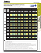
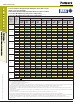
7/8 or #7
3-1/2 4,020 4,930 4,175 5,605 4,430 6,855 4,830 9,100 5,120 11,085
7 10,885 16,605 11,125 18,865 11,515 22,225 12,090 27,755 12,515 32,495
10-1/2 16,325 31,290 16,690 34,575 17,275 40,480 18,135 50,550 18,770 58,400
17-1/2 27,210 66,665 27,815 73,670 28,790 86,245 30,225 94,035 31,285 97,335
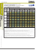
1 or #8
4 5,070 6,115 5,265 6,945 5,590 8,495 6,090 11,280 6,475 13,800
8 13,810 19,750 14,115 22,435 14,610 26,830 15,340 33,510 15,880 39,230
12 20,715 37,770 21,170 41,740 21,915 48,870 23,010 61,030 23,815 71,450
20 34,525 80,485 35,285 88,940 36,525 104,130 38,345 119,300 39,695 123,495
■ - Concrete Breakout Strength ■ - Bond Strength/Pryout Strength
1. Tabular values are provided for illustration and are applicable for single anchors installed in uncracked normal-weight concrete with minimum slab thickness,
h
a
= h
min
, and with the following conditions:
- c
a1
is greater than or equal to the critical edge distance, c
ac
- c
a2
is greater than or equal to 1.5 times c
a1
.
2. Calculations were performed following methodology in ACI 318-11 Appendix D and ICC-ES AC308. The load level corresponding to the failure mode listed [Concrete breakout strength,
bond strength/pryout strength] must be checked against the tabulated steel strength of the corresponding threaded rod or rebar size and type, the lowest load level controls. This
temperature range is not recognized by ACI 318-11 and does not meet the minimum temperature requirements from ACI 355.4 Table 8.1 and consequently is not
applicable to design under ACI 318-11 or current and past editions of the international building code (IBC). The tabulated values are provided for analysis and
evaluation of existing conditions only.
3. Strength reduction factors (
f
) for concrete breakout strength are based on ACI 318 Section 9.2 for load combinations. Condition B was assumed.
4. Strength reduction factors (
f
) for bond strength are determined from reliability testing and qualification in accordance with ICC-ES AC308 and are tabulated in this product information
and in ESR-2583.
5. Tabular values are permitted for short-term static loads only, seismic loading is not considered with these tables.
6. For designs that include combined tension and shear, the interaction of tension and shear loads must be calculated in accordance with ACI 318-11 Appendix D.
7. Interpolation is not permitted to be used with the tabular values. For intermediate base material compressive strengths, please see ACI 318-11 Appendix D, ICC-ES AC308 and information
included in this product supplement. For other design conditions including seismic considerations please see ACI 318-11 Appendix D and ICC-ES AC308 and ESR-2583.
8. Long term concrete temperatures are roughly constant over significant periods of time. Short-term elevated temperatures are those that occur over brief intervals, e.g. as a result of
diurnal cycling.