
pdf-doc

aDhesiVe anchors
www.powers.com
12
TECH MANUAL – ADHESIVE ANCHORS ©2015 POWERS VOLUME 1 – 9/2015 – REV. G
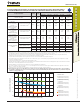
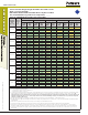
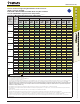
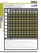
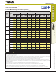
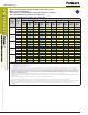
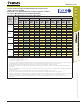
STRENGTH DESIGN (SD)
Tension and Shear Design Strength Installed in Uncracked Concrete
(Bond or Concrete Strength)
Drilled with a Hammer-Drill and Carbide Bit in a Dry Hole Condition
75°F (24°C) Maximum Long-Term Service Temperature;
104°F (40°C) Maximum Short-Term Service Temperature
1,2,3,4,5,6,7,8
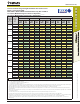
Nominal
Rod/Rebar
Size
(in. or #)
Embed.
Depth
h
ef
(in.)
Minimum Concrete Compressive Strength
f'c = 2,500 psi f'c = 3,000 psi f'c = 4,000 psi f'c = 6,000 psi f'c = 8,000 psi
Φ
Ncb
or
Φ
Na
Tension
(lbs.)
Φ
Vcb or
Φ
Vcp
Shear
(lbs.)
Φ
Ncb
or
Φ
Na
Tension
(lbs.)
Φ
Vcb or
Φ
Vcp
Shear
(lbs.)
Φ
Ncb
or
Φ
Na
Tension
(lbs.)
Φ
Vcb or
Φ
Vcp
Shear
(lbs.)
Φ
Ncb
or
Φ
Na
Tension
(lbs.)
Φ
Vcb or
Φ
Vcp
Shear
(lbs.)
Φ
Ncb
or
Φ
Na
Tension
(lbs.)
Φ
Vcb or
Φ
Vcp
Shear
(lbs.)
3/8 or #3
2-3/8 2,855 2,570 3,125 2,920 3,610 3,575 4,425 4,745 4,965 5,350
3 4,055 4,010 4,440 4,555 5,125 5,570 6,060 7,295 6,275 8,540
4-1/2 7,445 7,935 8,155 9,015 8,660 10,660 9,090 13,315 9,410 15,585
1/2 or #4
2-3/4 3,555 3,305 3,895 3,755 4,500 4,590 5,510 6,095 6,365 7,455
4 6,240 6,700 6,835 7,610 7,895 9,310 9,665 12,365 10,535 14,780
6 11,465 13,235 12,560 15,035 14,500 18,390 15,270 22,995 15,805 26,920
10 22,910 30,315 23,420 33,500 24,240 39,220 25,450 48,975 26,345 56,740
5/8 or #5
3-1/8 4,310 4,120 4,720 4,680 5,450 5,720 6,675 7,600 7,710 9,295
5 8,720 9,985 9,555 11,345 11,030 13,875 13,510 18,430 15,600 22,540
7-1/2 16,020 19,725 17,550 22,410 20,265 27,410 22,840 35,210 23,640 41,225
12-1/2 34,270 46,440 35,025 51,320 36,255 60,085 38,065 75,035 39,400 84,865
3/4 or #6
3-1/2 5,105 5,015 5,595 5,700 6,460 6,970 7,910 9,255 9,135 11,320
6 11,465 13,595 12,560 15,445 14,500 18,895 17,760 25,095 20,505 30,695
9 21,060 26,855 23,070 30,510 26,640 37,320 31,740 49,025 32,855 57,395
15 45,315 63,370 48,675 71,435 50,385 83,635 52,900 104,445 54,755 117,935
7/8 or #7
3-1/2 5,105 4,930 5,595 5,605 6,460 6,855 7,910 9,100 9,135 11,130
7 14,445 16,605 15,825 18,865 18,275 23,075 22,380 30,650 25,840 37,485
10-1/2 26,540 32,800 29,070 37,265 33,570 45,580 41,115 60,540 43,425 71,450
17-1/2 57,100 77,405 62,550 87,940 66,595 104,125 69,915 130,030 72,370 152,235
1 or #8
4 6,240 6,115 6,835 6,945 7,895 8,495 9,665 11,280 11,160 13,800
8 17,650 19,750 19,335 22,435 22,325 27,440 27,340 36,450 31,570 44,580
12 32,425 39,005 35,520 44,315 41,015 54,200 50,230 71,990 55,225 86,340
20 69,765 92,055 76,425 104,585 84,690 125,830 88,915 157,140 92,040 183,970
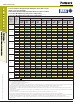
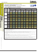
#9
4-1/2 7,445 7,110 8,155 8,080 9,420 9,880 11,535 13,125 13,320 16,055
9 21,060 23,055 23,070 26,190 26,640 32,035 32,625 42,550 37,675 52,040
13-1/2 38,690 45,540 42,380 51,740 48,940 63,280 59,940 84,050 68,320 102,275
22-1/2 83,245 107,440 91,190 122,065 104,780 149,000 110,005 186,075 113,870 217,845
1-1/4
5 8,720 8,170 9,555 9,285 11,030 11,355 13,510 15,085 15,600 18,450
10 24,665 26,380 27,020 29,975 31,200 36,660 38,210 48,690 44,125 59,555
15 45,315 52,110 49,640 59,200 57,320 72,410 70,200 96,175 81,060 117,630
25 97,500 122,990 106,805 139,730 123,330 170,905 132,975 215,715 137,645 252,550
#10
5 8,720 8,160 9,555 9,270 11,030 11,335 13,510 15,060 15,600 18,420
10 24,665 26,430 27,020 30,025 31,200 36,725 38,210 48,780 44,125 59,660
15 45,315 52,205 49,640 59,310 57,320 72,545 70,200 96,350 81,060 117,845
25 97,500 123,170 106,805 139,935 123,330 171,155 132,975 216,030 137,645 252,920
■ - Concrete Breakout Strength ■ - Bond Strength/Pryout Strength
1. Tabular values are provided for illustration and are applicable for single anchors installed in uncracked normal-weight concrete with minimum slab thickness,
h
a
= h
min
, and with the following conditions:
- c
a1
is greater than or equal to the critical edge distance, c
ac
- c
a2
is greater than or equal to 1.5 times c
a1
.
2. Calculations were performed following methodology in ACI 318-11 Appendix D and ICC-ES AC308. The load level corresponding to the failure mode listed [Concrete breakout strength,
bond strength/pryout strength] must be checked against the tabulated steel strength of the corresponding threaded rod or rebar size and type, the lowest load level controls. This
temperature range is not recognized by ACI 318-11 and does not meet the minimum temperature requirements from ACI 355.4 Table 8.1 and consequently is not
applicable to design under ACI 318-11 or current and past editions of the international building code (IBC). The tabulated values are provided for analysis and
evaluation of existing conditions only.
3. Strength reduction factors (
f
) for concrete breakout strength are based on ACI 318 Section 9.2 for load combinations. Condition B was assumed.
4. Strength reduction factors (
f
) for bond strength are determined from reliability testing and qualification in accordance with ICC-ES AC308 and are tabulated in this product information
and in ESR-2583.
5. Tabular values are permitted for short-term static loads only, seismic loading is not considered with these tables.
6. For designs that include combined tension and shear, the interaction of tension and shear loads must be calculated in accordance with ACI 318-11 Appendix D.
7. Interpolation is not permitted to be used with the tabular values. For intermediate base material compressive strengths, please see ACI 318-11 Appendix D, ICC-ES AC308 and
information included in this product supplement. For other design conditions including seismic considerations please see ACI 318-11 Appendix D and ICC-ES AC308 and ESR-2583.
8. Long term concrete temperatures are roughly constant over significant periods of time. Short-term elevated temperatures are those that occur over brief intervals, e.g. as a result of
diurnal cycling.