
User's Manual

Device Solutions Inc
Proprietary and Confidential
4. Tin the ends of the transducer cable with a
soldering iron.
5. Trim the transducer wire such that only
0.25 inches remains uninsulated.
6. Inspect the transducer cable for loose
solder and wire strands. Repeat steps 3
through 6 if found. Loose solder or wire
strands can cause permanent damage to
the Sensor and/or transducer.
7. Remove the battery from the Sensor.
Performing the following steps with the
battery installed can lead to permanent
damage of the device.
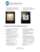
8. Loosen the nut from the outside of the
cable restraint shown above.
9. Pass the transducer wires through the cable
restraint.
10. Tighten the cable restraint nut to the cable
restraint. Note: The transducer cable must
be between 2.9 and 6.4 mm in diameter
and must be tighten to a torque of 25-30
inch lbs to avoid water infiltration.
11. Attach the transducer wires to the terminal
blocks. This connection depends on the
type of transducer used.
12. Install the 9 volt battery in the sensor
13. Re-install the screws that hold the top of
the enclosure to the baseplate.
14. Attach the enclosure to a surface. The best
RF performance is obtained by mounting
the Sensor vertically. This is achieved with
the power connector coming out the left
side of the gateway.