
User's Manual

Device Solutions Inc
Proprietary and Confidential
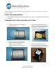
6. Place the FCC label on the bottom of the
enclosure as shown. The top of the label
should be pointing in the same direction
as the sensor antenna.
7. Apply the label as shown to the
enclosure. The top of the label should be
pointing in the same direction as the
sensor antenna.
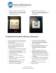
5 Example Host Product Installation Instructions
1. Use a Torx T10 driver to remove the screws
that hold the top of the Sensor's enclosure
to the baseplate.
2. Verify the signal strength at the Sensor.
Note: This signal strength monitoring
process may only be executed on one
Sensor at a time.
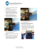
a. Open the Gateway by using a Torx T10 bit
to remove the four screws which hold the
enclosure top to the base plate.
b. Press the button on the Gateway to enter
"Range Check Mode".
c. Wait for the internal green LED to
illuminate.
d. Place the Sensor within 50 feet line of
sight of the Gateway
e. Reboot the Sensor by removing and re-
installing the 9 volt battery
f. Wait for the Sensor's internal LED to
illuminate (up to 10 seconds)
g. The color of the LED indicates the
following (red – poor signal quality,
yellow – marginal signal quality, green –
good signal quality)
h. Move the Gateway and/or Sensor until
the Sensor displays a good signal
condition for at least 5 consecutive
seconds.
i. Repeat c through g for each sensor.
j. Disable "Range Check Mode" for the
Gateway by pressing the button on the
Gateway again (if this step is forgotten
the Gateway will exit Range Check Mode
in one hour)
k. Turn off each Sensor by removing the 9
volt battery (if this step is forgotten the
sensor will exit install mode in five
minutes)
3. Strip the insulation from the end of
transducer wires.