
User's Manual

Device Solutions Inc
Proprietary and Confidential
Changes or modifications not expressly approved by the party responsible for compliance could void the user's authority to
operate the equipment.
3 Other Recommendations
1. The PA0022 Sensor II LoRa board shall be installed in such a way as to maximize clearance around the
antenna.
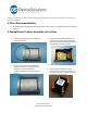
4 Example Host Product Assembly Instructions
1. Insert the rubber O-ring into the groove in
the enclosure base.
2. Insert the wire gland in the bulkhead as
shown and fasten in place with the wire
grommet nut on the inside of the
enclosure bulkhead to a torque of 15-20
inch lbs.
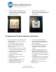
3. Fasten the Sensor PCB assembly to the
enclosure top using four 3/8” #4 screws
as shown. The screws should be tight such
that the PCB is not free to move.
4. Install the battery retention device.
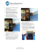
5. Insert four 3/8” #4 screws into the
corners of the enclosure top to fasten it
to the enclosure base. Tighten screws to a
torque of 8.2 +/-0.5 kgf-cm.