
User's Manual

10. Insert the external power plug into the jack and
tighten the locking ring. Failure to properly tighten
the locking ring will invalidate the IP68 rating of the
Gateway.
4
Sensor Installation
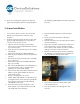
1. Use a Torx T10 driver to remove the screws that
hold the top of the Sensor's enclosure to the
baseplate.
2. Verify the signal strength at the Sensor. Note: This
signal strength monitoring process may only be
executed on one Sensor at a time.
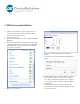
a. Open the Gateway by using a Torx T10 bit to
remove the four screws which hold the enclosure
top to the base plate.
b. Press the button on the Gateway to enter "Range
Check Mode".
c. Wait for the internal green LED to illuminate.
d. Place the Sensor within 50 feet line of sight of the
Gateway
e. Reboot the Sensor by removing and re-installing
the 9 volt battery
f. Wait for the Sensor's internal LED to illuminate
(up to 10 seconds)
g. The color of the LED indicates the following (red –
poor signal quality, yellow – marginal signal
quality, green – good signal quality)
h. Move the Gateway and/or Sensor until the Sensor
displays a good signal condition for at least 5
consecutive seconds.
i. Repeat c through g for each sensor.
j. Disable "Range Check Mode" for the Gateway by
pressing the button on the Gateway again (if this
step is forgotten the Gateway will exit Range
Check Mode in one hour)
k. Turn off each Sensor by removing the 9 volt
battery (if this step is forgotten the sensor will
exit install mode in five minutes)
3. Strip the insulation from the end of transducer
wires.
4. Tin the ends of the transducer cable with a
soldering iron.
5. Trim the transducer wire such that only 0.25 inches
remains uninsulated.
6. Inspect the transducer cable for loose solder and
wire strands. Repeat steps 3 through 6 if found.
Loose solder or wire strands can cause permanent
damage to the Sensor and/or transducer.
7. Remove the battery from the Sensor. Performing
the following steps with the battery installed can
lead to permanent damage of the device.
8. Loosen the nut from the outside of the cable
restraint shown above.
9. Pass the transducer wires through the cable
restraint.