Device Solutions Gateway & Sensor Installation Instructions
1 FCC Interference Statement Changes or modifications not expressly approved by Device Solutions could void the user’s authority to operate this equipment. Note: This equipment has been tested and found to comply with the limits for a Class B digital device, pursuant to part 15 of the FCC Rules. These limits are designed to provide reasonable protection against harmful interference in a residential installation.
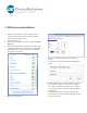
WiFi Gateway Installation 1. Using a Torx T10 driver, remove the four 3/8” #4 screws into the corners of the enclosure top that fasten it to the enclosure base. 2. Connect the battery. 3. Press the button on the Gateway, the green LED will illuminate. 4. The Gateway has become a WiFi Access Point. Using a laptop or similar device connect to the “DS-Cellio” network. This is an unsecured connection and does not require a password. 6. Locate the desired system and press the Join button. 7.
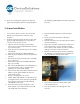
10. Insert the external power plug into the jack and tighten the locking ring. Failure to properly tighten the locking ring will invalidate the IP68 rating of the Gateway. 4 Sensor Installation 1. Use a Torx T10 driver to remove the screws that hold the top of the Sensor's enclosure to the baseplate. 2. Verify the signal strength at the Sensor. Note: This signal strength monitoring process may only be executed on one Sensor at a time. a.
10. Tighten the cable restraint nut to the cable restraint. Note: The transducer cable must be between 2.9 and 6.4 mm in diameter and must be tighten to a torque of 25-30 inch lbs to avoid water infiltration. 11. Attach the transducer wires to the terminal blocks. This connection depends on the type of transducer used. 12. Install the 9 volt battery in the sensor 13. Re-install the screws that hold the top of the enclosure to the baseplate. 14. Attach the enclosure to a surface.