
Parallax P2 Edge Module - User Guide

external pull-up resistors by default, and are completely flexible and free for the user to use as
required.
In user code those pins could be driven high or low, or have I/O pin pull-ups activated, to control
the LEDs without the high-impedance behaviour.
If the LEDs are not required, the P2 Edge Module dip-switch marked “LED” could be switched
“OFF” to disable LED power.
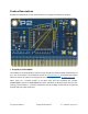
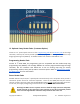
8. LEDs P56 and P57
These two LEDs are mounted so that they are visible from both sides of the P2 Edge Module
PCB. They are connected via an LED Buffer to pins P56 and P57. The buffer isolates the LEDs so
they will not influence the I/O signals.
If the LEDs are not required, the P2 Edge Module dip-switch marked “LED” could be switched
“OFF” to disable LED power.
9. Mounting Holes
The two plated mounting holes are attached to the ground plane. See the PCB Dimensions
section for mounting hole spacing.
10. Orientation Hole
The single unplated orientation hole could be used by a customer application to fix the module
in-place or ensure correct orientation. See the PCB Dimensions section for the hole position and
dimensions.
11. Edge connector
The 0.05” (1.27 mm) pitch 8- way edge connector extends on both sides of the module, with 40
connections on each side. Refer to Edge Connector Pin Assignment for full details.
Suitable connectors are available from the Parallax webshop:
● Card Edge Socket, Through Hole, Right Angle (#450-00308)
● Card Edge Socket, Straight, SMT (#450-00309)
● Card Edge Socket, Straight, Through Hole (#450-00310)
Copyright © Parallax Inc. P2 Edge Module (#P2-EC) v1.7 4/15/2021 Page 7 of 12