
Parallax P2 Edge Module - User Guide

Tip: △ and ▽ are both connected to the Propeller 2 I/O pin P59; one with a pull-up resistor to
3.3V, and the other with a pull-down resistor to GND. You may see these boot mode selection
pins referred to in other documentation as P59 up and P59 down.
Important! To avoid inconsistent behavior, only switch one of the △ or ▽ dip-switches ON.
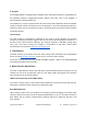
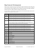
Boot Mode Selection
FLASH
△
▽
Serial window of 60 seconds, default.
(When SD card is NOT inserted)
OFF
OFF
OFF
Serial window of 60 seconds, overrides SPI Flash and SD card.
ON or OFF
ON
OFF
Serial window of 100 ms, then SPI flash.
If SPI flash fails then serial window of 60 seconds.
ON
OFF
OFF
SPI flash only (fast boot), no serial window.
If SPI flash fails then shutdown.
ON
OFF
ON
SD card with serial window on failure.
If SD card fails then serial window of 60 seconds.
OFF
OFF
OFF
SD card only, no serial window.
If SD card fails then shutdown.
OFF
OFF
ON
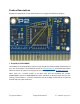
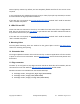
Tip: If required for booting, an SD card socket can be connected to the P2 Edge Module’s edge
connector, perhaps on a breakout board, using these connections:
● P58 - DI/CD (data in and card detect)
● P59 - DO (data out)
● P60 - /CS (active low chip select).
● P61 - CLK (clock)
● V56 - 3.3V power to the microSD card socket
● Common Gnd between P2 Edge module and microSD card socket
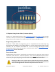
7. LED Buffer
The LED buffer is a dual Schmitt-trigger buffer that has high impedance connections to the P2
microprocessor I/Os P56 and P57, and drives the corresponding status LED ON when the P2 I/O
signal line is high.
All I/O signals from the P2 microcontroller are high impedance by default, which means the
LEDs will be sensitive to objects moving close to the edge connector P56 and P57 pins. This
design choice means that those 2 I/O pins are not impacted by the presence of the LEDs or
Copyright © Parallax Inc. P2 Edge Module (#P2-EC) v1.7 4/15/2021 Page 6 of 12