
Parallax P2 Edge Module - Datasheet
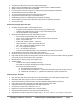
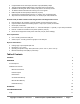
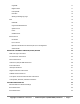
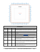
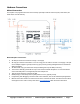
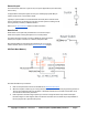
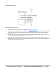
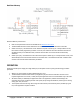
Table Of Contents
- FEATURES
- HARDWARE
- Pin Descriptions
- Hardware Connections
- Minimal Connections
- External Crystal
- Reset Switch
- SPI Flash Boot Memory
- MicroSD Boot Memory
- Dual Boot Memory
- OPERATION
- SYSTEM ORGANIZATION
- Cogs
- Cog RAM
- Register RAM
- Lookup RAM
- Execution
- Hub
- Hub RAM
- Cog-to-Hub RAM Interface
- System Clock
- CORDIC Solver
- Smart I/O Pins
- Pin Modes
- I/O Pin Circuit
- Equivalent Schematics
- Smart Modes
- PASM2 LANGUAGE IN BRIEF
- Math and Logic
- Pin & Smart Pin
- Branch
- Hub Control, FIFO, & RAM
- Event
- Interrupt
- Register Indirection
- CORDIC Solver
- Color Space Converter and Pixel Mixer
- Lookup Table, Streamer, and Misc
- SYSTEM CHARACTERISTICS
- Absolute Maximum Electrical Ratings
- DC Characteristics
- AC Characteristics
- PACKAGING
- CHANGE LOG
- PARALLAX INCORPORATED

MicroSD Boot Memory
MicroSD Boot Memory Connections
● Refer to all requirements and recommendations for Minimal Connections
● When the Propeller 2 starts up (or is reset) with this circuit, it will automatically boot from firmware saved
on the microSD card. If microSD boot fails, a further serial window of 60 seconds will be followed by
shutdown.
● The microSD card must be formatted as FAT32, and the boot firmware file must be saved in the root of
the microSD card with the special filename: _P2_BOOT.BIX
● Each Propeller 2 firmware image requires up to 512 KB. A single microSD card could hold multiple
firmware images or code snippets, and/or be used for user data. The microSD card is fully available to the
user program as a general memory area.
Copyright © Parallax Inc. 2021/05/27 ▪ Parallax Propeller 2 (P2X8C4M64P) Datasheet ▪ Page 9