
Parallax P2 Edge Module - Datasheet
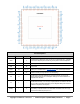
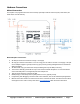
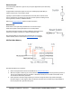
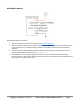
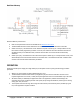
Table Of Contents
- FEATURES
- HARDWARE
- Pin Descriptions
- Hardware Connections
- Minimal Connections
- External Crystal
- Reset Switch
- SPI Flash Boot Memory
- MicroSD Boot Memory
- Dual Boot Memory
- OPERATION
- SYSTEM ORGANIZATION
- Cogs
- Cog RAM
- Register RAM
- Lookup RAM
- Execution
- Hub
- Hub RAM
- Cog-to-Hub RAM Interface
- System Clock
- CORDIC Solver
- Smart I/O Pins
- Pin Modes
- I/O Pin Circuit
- Equivalent Schematics
- Smart Modes
- PASM2 LANGUAGE IN BRIEF
- Math and Logic
- Pin & Smart Pin
- Branch
- Hub Control, FIFO, & RAM
- Event
- Interrupt
- Register Indirection
- CORDIC Solver
- Color Space Converter and Pixel Mixer
- Lookup Table, Streamer, and Misc
- SYSTEM CHARACTERISTICS
- Absolute Maximum Electrical Ratings
- DC Characteristics
- AC Characteristics
- PACKAGING
- CHANGE LOG
- PARALLAX INCORPORATED

External Crystal
The internal clock reference is good for very low power applications, but is also fairly
low accuracy.
For applications that require higher accuracy (ex: handling high speed data) an
external clock source is connected to XI/XO.
Typically a crystal would be connected between XI and XO, but an external clock
source could also be connected to XI only, with common options including a clock
source generator, oscillator, or MEMS resonator.
Refer to the AC Characteristics table for further information.
Reset Switch
Reset Switch can be optionally included and is a convenient way to
restart the Propeller 2 during development or in a final product.
The switch drives the Propeller 2 reset pin (RESN) to ground, and while
held low, the Propeller 2 remains in a dormant, low-power state.
Note that the RESN pin must always be pulled high (to 3.3 V) with an
external resistor, which is shown in the Minimal Connections diagram.
SPI Flash Boot Memory
SPI Flash Boot Memory Connections
● Refer to all requirements and recommendations for Minimal Connections
● When the Propeller 2 starts up (or is reset) with this circuit, there will be a serial programming window of
100 ms, then automatic boot from SPI flash. If SPI flash boot fails, then a further serial window of 60
seconds will be followed by shutdown.
● Each Propeller 2 firmware image requires up to 512 KB. A single SPI Flash chip could hold multiple
firmware images or code snippets, and/or be used for user data. The SPI Flash chip is fully available to
the user program as a general memory area.
Copyright © Parallax Inc. 2021/05/27 ▪ Parallax Propeller 2 (P2X8C4M64P) Datasheet ▪ Page 8