
Parallax P2 Edge Module - Datasheet
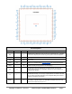
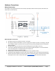
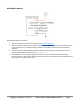
Table Of Contents
- FEATURES
- HARDWARE
- Pin Descriptions
- Hardware Connections
- Minimal Connections
- External Crystal
- Reset Switch
- SPI Flash Boot Memory
- MicroSD Boot Memory
- Dual Boot Memory
- OPERATION
- SYSTEM ORGANIZATION
- Cogs
- Cog RAM
- Register RAM
- Lookup RAM
- Execution
- Hub
- Hub RAM
- Cog-to-Hub RAM Interface
- System Clock
- CORDIC Solver
- Smart I/O Pins
- Pin Modes
- I/O Pin Circuit
- Equivalent Schematics
- Smart Modes
- PASM2 LANGUAGE IN BRIEF
- Math and Logic
- Pin & Smart Pin
- Branch
- Hub Control, FIFO, & RAM
- Event
- Interrupt
- Register Indirection
- CORDIC Solver
- Color Space Converter and Pixel Mixer
- Lookup Table, Streamer, and Misc
- SYSTEM CHARACTERISTICS
- Absolute Maximum Electrical Ratings
- DC Characteristics
- AC Characteristics
- PACKAGING
- CHANGE LOG
- PARALLAX INCORPORATED

Hardware Connections
Minimal Connections
The Propeller 2 is programmed via four wires and may optionally include an external crystal, reset switch, SPI
Flash and/or microSD memory.
Minimal Propeller 2 Connections
● All VDD pins must be connected to a single 1.8 V supply.
● All Vxxyy pins must be connected to 3.3 V. The Vxxyy pins can share a common 3.3 V supply, or be split
across multiple supplies. Typically those Vxxyy pins powering analog and digital functions would have
different supplies.
● All VDD and all Vxxyy pins must have closely-located bypass caps to GND (not shown).
● The common GND (EP) pad under the chip is also used for thermal dissipation. It is recommended to
connect the GND pad to a solid ground plane with multiple vias.
● TEST pin must always be connected to GND.
● RESN (reset) pin must always have a pullup resistor to 3.3 V (typically 10 KΩ).
● Programming and debugging is achieved with a serial interface, such as the Parallax PropPlug #32201.
● Minimal connections assume no external clock source connected to XI/XO– the internal clock must be
used (adjust source code to match). Refer to the AC Characteristics table for further information.
Copyright © Parallax Inc. 2021/05/27 ▪ Parallax Propeller 2 (P2X8C4M64P) Datasheet ▪ Page 7