
Parallax P2 Edge Module - Datasheet
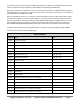
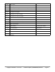
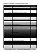
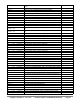
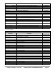

Table Of Contents
- FEATURES
- HARDWARE
- Pin Descriptions
- Hardware Connections
- Minimal Connections
- External Crystal
- Reset Switch
- SPI Flash Boot Memory
- MicroSD Boot Memory
- Dual Boot Memory
- OPERATION
- SYSTEM ORGANIZATION
- Cogs
- Cog RAM
- Register RAM
- Lookup RAM
- Execution
- Hub
- Hub RAM
- Cog-to-Hub RAM Interface
- System Clock
- CORDIC Solver
- Smart I/O Pins
- Pin Modes
- I/O Pin Circuit
- Equivalent Schematics
- Smart Modes
- PASM2 LANGUAGE IN BRIEF
- Math and Logic
- Pin & Smart Pin
- Branch
- Hub Control, FIFO, & RAM
- Event
- Interrupt
- Register Indirection
- CORDIC Solver
- Color Space Converter and Pixel Mixer
- Lookup Table, Streamer, and Misc
- SYSTEM CHARACTERISTICS
- Absolute Maximum Electrical Ratings
- DC Characteristics
- AC Characteristics
- PACKAGING
- CHANGE LOG
- PARALLAX INCORPORATED

any number of cogs can read a smart pin simultaneously without bus conflict by using RQPIN ('read quiet'), since
it does not utilize the smart pin input bus for acknowledgement signalling (like RDPIN does).
Each smart pin writes to it's output bus to convey its Z result and a special flag. The RDPIN and RQPIN multiplex
and read these buses, so that a pin's Z result is read into D and its special flag can be read into C. C will be either a
mode-related flag or the MSB of the Z result.
When a mode-related event occurs in a smart pin, it raises its IN signal to alert the cog(s) that new data is ready,
new data can be loaded, or some process has finished. A cog can test for this signal via the TESTP instruction
and can acknowledge a smart pin by executing a WRPIN, WXPIN, WYPIN, RDPIN, or AKPIN instruction for it. This
acknowledgement causes the smart pin to lower its IN signal so that it can be raised again on the next event.
After a WRPIN/WXPIN/WYPIN/RDPIN/AKPIN, it takes two clocks for IN to drop, before it can be polled again.
A smart pin can be reset at any time, without the need to reconfigure it, by clearing and then setting its DIR bit.
To return a pin to normal mode, do a 'WRPIN #0,pin'.
Smart Pin Modes
%SSSSS
Mode
Note
00000
smart pin off (default)
00001
long repository
M[12:10] != %101
00010
long repository
M[12:10] != %101
00011
long repository
M[12:10] != %101
00001
DAC noise
M[12:10] = %101
00010
DAC 16-bit dither, noise
M[12:10] = %101
00011
DAC 16-bit dither, PWM
M[12:10] = %101
00100
1
pulse/cycle output
00101
1
transition output
00110
1
NCO frequency
00111
1
NCO duty
01000
1
PWM triangle
01001
1
PWM sawtooth
01010
1
PWM switch-mode power supply, V and I feedback
01011
periodic/continuous: A-B quadrature encoder
01100
periodic/continuous: inc on A-rise & B-high
01101
periodic/continuous: inc on A-rise & B-high / dec on A-rise & B-low
01110
periodic/continuous: inc on A-rise {/ dec on B-rise}
01111
periodic/continuous: inc on A-high {/ dec on B-high}
Copyright © Parallax Inc. 2021/05/27 ▪ Parallax Propeller 2 (P2X8C4M64P) Datasheet ▪ Page 31