
Parallax P2 Edge Module - Datasheet
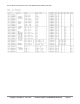
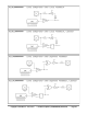
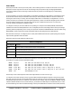
Table Of Contents
- FEATURES
- HARDWARE
- Pin Descriptions
- Hardware Connections
- Minimal Connections
- External Crystal
- Reset Switch
- SPI Flash Boot Memory
- MicroSD Boot Memory
- Dual Boot Memory
- OPERATION
- SYSTEM ORGANIZATION
- Cogs
- Cog RAM
- Register RAM
- Lookup RAM
- Execution
- Hub
- Hub RAM
- Cog-to-Hub RAM Interface
- System Clock
- CORDIC Solver
- Smart I/O Pins
- Pin Modes
- I/O Pin Circuit
- Equivalent Schematics
- Smart Modes
- PASM2 LANGUAGE IN BRIEF
- Math and Logic
- Pin & Smart Pin
- Branch
- Hub Control, FIFO, & RAM
- Event
- Interrupt
- Register Indirection
- CORDIC Solver
- Color Space Converter and Pixel Mixer
- Lookup Table, Streamer, and Misc
- SYSTEM CHARACTERISTICS
- Absolute Maximum Electrical Ratings
- DC Characteristics
- AC Characteristics
- PACKAGING
- CHANGE LOG
- PARALLAX INCORPORATED

Smart Modes
Each I/O pin has built-in 'smart pin' circuitry which, when enabled, performs an autonomous function on the pin.
Smart pins free the cogs from the need to micromanage many I/O operations by providing high-bandwidth
concurrent hardware functions that cogs could otherwise not perform as well through I/O pin manipulating
instructions.
In normal operation, an I/O pin's output enable is controlled by its DIR bit, its output state is controlled by its OUT
bit, and its IN bit returns the pin's read state. With smart pin mode enabled, its DIR bit is used as an active-low
reset signal to the smart pin circuitry, while the output enable state is controlled by a configuration bit. In some
modes, the smart pin circuit takes over driving the output state, in which case the OUT bit gets ignored. Its IN bit
serves as a flag to indicate to the cog(s) that the smart pin has completed some function or an event has
occurred, and acknowledgment is perhaps needed.
To configure a smart pin, first set its DIR bit to low (holding it in reset) then use WRPIN, WXPIN, and WYPIN to
establish the mode and related parameters. Once configured, DIR can be raised high and the smart pin will begin
operating. After that, depending on the mode, you may feed it new data via WXPIN/WYPIN or retrieve results using
RDPIN/RQPIN. These activities are usually coordinated with the IN signal going high; explained later.
Note that while a smart pin is configured, the %TT bits (of the WRPIN instruction's D operand) will govern the pin's
output enable, regardless of the DIR state.
Smart pins have four 32-bit registers inside of them:
Smart Pin Registers
32-bit Register
Purpose
Mode
smart pin mode, as well as low-level I/O pin mode (write-only)
X
mode-specific parameter (write-only)
Y
mode-specific parameter (write-only)
Z
mode-specific result (read-only)
These four registers are written and read via the following 2-clock instructions, in which S/# is used to select the
pin number (0..63) and D/# is the 32-bit data conduit:
WRPIN D/#,S/# - Set smart pin S/# mode to D/#, ack pin
WXPIN D/#,S/# - Set smart pin S/# parameter X to D/#, ack pin
WYPIN D/#,S/# - Set smart pin S/# parameter Y to D/#, ack pin
RDPIN D,S/# {WC} - Get smart pin S/# result Z into D, flag into C, ack pin
RQPIN D,S/# {WC} - Get smart pin S/# result Z into D, flag into C, don't ack pin
AKPIN S/# - Acknowledge pin S/#
Each smart pin has a 34-bit input bus and a 33-bit output bus that connect it to the cogs.
To configure and control smart pins, each cog writes data and acknowledgement signals to the smart pin input
bus. Each smart pin OR's all incoming 34-bit buses from the collective of cogs in the same way DIR and OUT bits
are OR'd before going to the pins. Therefore, if you intend to have multiple cogs execute WRPIN / WXPIN / WYPIN
/ RDPIN / AKPIN instructions on the same smart pin, you must be sure that they do so at different times, in order
to avoid clobbering each other's bus data. Reading a smart pin with RDPIN can cause the same conflict; however,
Copyright © Parallax Inc. 2021/05/27 ▪ Parallax Propeller 2 (P2X8C4M64P) Datasheet ▪ Page 30