
Parallax P2 Edge Module - Datasheet
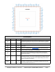
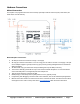
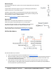
Table Of Contents
- FEATURES
- HARDWARE
- Pin Descriptions
- Hardware Connections
- Minimal Connections
- External Crystal
- Reset Switch
- SPI Flash Boot Memory
- MicroSD Boot Memory
- Dual Boot Memory
- OPERATION
- SYSTEM ORGANIZATION
- Cogs
- Cog RAM
- Register RAM
- Lookup RAM
- Execution
- Hub
- Hub RAM
- Cog-to-Hub RAM Interface
- System Clock
- CORDIC Solver
- Smart I/O Pins
- Pin Modes
- I/O Pin Circuit
- Equivalent Schematics
- Smart Modes
- PASM2 LANGUAGE IN BRIEF
- Math and Logic
- Pin & Smart Pin
- Branch
- Hub Control, FIFO, & RAM
- Event
- Interrupt
- Register Indirection
- CORDIC Solver
- Color Space Converter and Pixel Mixer
- Lookup Table, Streamer, and Misc
- SYSTEM CHARACTERISTICS
- Absolute Maximum Electrical Ratings
- DC Characteristics
- AC Characteristics
- PACKAGING
- CHANGE LOG
- PARALLAX INCORPORATED

● 6-clock custom-bytecode executor for interpreted languages
● Ability to stream Hub RAM and/or Lookup RAM to DACs and pins or HDMI modulator
● Ability to stream pins and/or ADCs to Hub RAM
● Live colorspace conversion using a 3 x 3 matrix with 8-bit signed/unsigned coefficients
● Pixel blending instructions for 8:8:8:8 data
● 16 unique event trackers that can be polled and waited upon
● 3 prioritized interrupts that trigger on selectable events
● Hidden debug interrupt for single-stepping, breakpoint, and polling
● 8-level hardware stack for fastest subroutine calls/returns and push/pop operations
● Carry and Zero flag
Central hub serving the processors with:
● 512 KB of contiguous RAM in a 20-bit address space
○ 32-bits-per-clock sequential read/write for all cogs, simultaneously
○ readable and writable as bytes, words, or longs in little-endian format
○ last 16 KB of RAM is write-protectable
● 32-bit, pipelined CORDIC solver with scale-factor correction
○ 32-bit x 32-bit unsigned multiply with 64-bit result
○ 64-bit / 32-bit unsigned divide with 32-bit quotient and 32-bit remainder
○ 64-bit → 32-bit square root
○ Rotate (X32, Y32) by Theta32 → (X32, Y32)
○ (Rho32, Theta32) → (X32, Y32) polar-to-cartesian
○ (X32, Y32) → (Rho32, Theta32) cartesian-to-polar
○ 32 → 5.27 unsigned-to-logarithm
○ 5.27 → 32 logarithm-to-unsigned
○ Cogs can start CORDIC operations every 8 clocks and get results 55 clocks later
● 16 semaphore bits with atomic read-modify-write operations
● 64-bit free-running counter which increments every clock, cleared on reset
● High-quality pseudo-random number generator (Xoroshiro128**), true-random seeded at start-up, updates
every clock, provides unique data to each cog and pin
● Mechanisms for starting, polling, and stopping cogs
● 16KB boot ROM
○ Loads into last 16 KB of Hub RAM on boot-up
○ SPI loader for automatic startup from 8-pin flash or SD card
○ Serial loader for startup from host
■ Hex and Base64 download protocols
■ Terminal monitor invocable via "> " (greater than followed by a space) and then CTRL+D
■ TAQOZ Forth invocable via "> " (greater than followed by a space) and then ESC
64 Smart I/O pins, each with:
● 8-bit, 120-ohm (3ns) and 1k-ohm DACs with 16-bit oversampling, noise, and high/low digital modes
● Delta-sigma ADC with 5 ranges, 2 sources, and VIO/GIO calibration
● Several ADC sampling modes: automatic 2n SINC2, adjustable SINC2/SINC3, oscilloscope
● Logic, Schmitt, pin-to-pin-comparator, and 8-bit-level-comparator input modes
● 2/3/5/8-bit-unanimous input filtering with selectable sample rate
● Incorporation of inputs from relative pins, -3 to +3
● Negative or positive local feedback, with or without clocking
● Externally powered in blocks of 4 for clean analog Vdd reference
● Separate drive modes for high and low output: logic / 1.5 k / 15 k / 150 k / 1 mA / 100 µA / 10 µA / float
Copyright © Parallax Inc. 2021/05/27 ▪ Parallax Propeller 2 (P2X8C4M64P) Datasheet ▪ Page 2