
Parallax P2 Edge Module - Datasheet
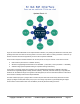
Table Of Contents
- FEATURES
- HARDWARE
- Pin Descriptions
- Hardware Connections
- Minimal Connections
- External Crystal
- Reset Switch
- SPI Flash Boot Memory
- MicroSD Boot Memory
- Dual Boot Memory
- OPERATION
- SYSTEM ORGANIZATION
- Cogs
- Cog RAM
- Register RAM
- Lookup RAM
- Execution
- Hub
- Hub RAM
- Cog-to-Hub RAM Interface
- System Clock
- CORDIC Solver
- Smart I/O Pins
- Pin Modes
- I/O Pin Circuit
- Equivalent Schematics
- Smart Modes
- PASM2 LANGUAGE IN BRIEF
- Math and Logic
- Pin & Smart Pin
- Branch
- Hub Control, FIFO, & RAM
- Event
- Interrupt
- Register Indirection
- CORDIC Solver
- Color Space Converter and Pixel Mixer
- Lookup Table, Streamer, and Misc
- SYSTEM CHARACTERISTICS
- Absolute Maximum Electrical Ratings
- DC Characteristics
- AC Characteristics
- PACKAGING
- CHANGE LOG
- PARALLAX INCORPORATED

Square Root
Use the QSQRT instruction on a 64-bit number and retrieve the square root CORDIC result with the GETQX
instruction.
(X, Y) Rotation
Use the SETQ instruction followed by the QROTATE instruction to rotate a 32-bit signed Y and X point pair by an
unsigned 32-bit angle and retrieve the CORDIC results with the GETQX and GETQY instructions for X and Y,
respectively.
(X, Y) to (length, angle)
Use the QVECTOR instruction to convert a (X, Y) cartesian coordinate into (length, angle) polar coordinate and
retrieve the CORDIC results with the GETQX and GETQY instructions (for length and angle, respectively).
(length, angle) to (X, Y)
Use the QROTATE instruction to convert a (length, angle) polar coordinate into (X, Y) cartesian coordinate and
retrieve the CORDIC results with the GETQX and GETQY instructions (for X and Y, respectively).
Logarithm
Use the QLOG instruction on an unsigned 32-bit integer and retrieve the 5:27-bit logarithm CORDIC result (5-bit
exponent and 27-bit mantissa) with the GETQX instruction.
Exponent
Use the QEXP instruction on a 5:27-bit logarithm and retrieve the unsigned 32-bit integer CORDIC result with the
GETQX instruction.
Smart I/O Pins
Every I/O pin features versatile digital and analog capabilities as well as autonomous state machine functions
that would otherwise require processor time to perform. The combination provides adept functionality for
application design, increasing the Propeller 2 potential beyond what multi-core architecture alone provides.
There are 24 low-level 'pin' modes and 34 high-level 'smart' modes.
Pin Modes
Each I/O pin has 13 low-level pin mode configuration bits which determine the operation of its 3.3 V circuit. The
pin mode is set using the WRPIN instruction, where the 13 %MMMMMMMMMMMMM bits within the instruction's
D operand go directly to these bits. Note though that in some smart pin modes, these bits are partially overwritten
to set things like DAC values.
The format of the D operand value is:
%AAAA_BBBB_FFF_MMMMMMMMMMMMM_TT_SSSSS_0
● A = PINA input selector
● B = PINB input selector
● F = PINA and PINB input logic/filtering (after PINA and PINB input selectors)
● M = pin mode
● T = pin DIR/OUT control (default = %00)
● S = smart mode
Copyright © Parallax Inc. 2021/05/27 ▪ Parallax Propeller 2 (P2X8C4M64P) Datasheet ▪ Page 19