
Parallax P2 Edge Module - Datasheet
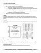
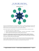
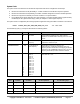
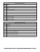
Table Of Contents
- FEATURES
- HARDWARE
- Pin Descriptions
- Hardware Connections
- Minimal Connections
- External Crystal
- Reset Switch
- SPI Flash Boot Memory
- MicroSD Boot Memory
- Dual Boot Memory
- OPERATION
- SYSTEM ORGANIZATION
- Cogs
- Cog RAM
- Register RAM
- Lookup RAM
- Execution
- Hub
- Hub RAM
- Cog-to-Hub RAM Interface
- System Clock
- CORDIC Solver
- Smart I/O Pins
- Pin Modes
- I/O Pin Circuit
- Equivalent Schematics
- Smart Modes
- PASM2 LANGUAGE IN BRIEF
- Math and Logic
- Pin & Smart Pin
- Branch
- Hub Control, FIFO, & RAM
- Event
- Interrupt
- Register Indirection
- CORDIC Solver
- Color Space Converter and Pixel Mixer
- Lookup Table, Streamer, and Misc
- SYSTEM CHARACTERISTICS
- Absolute Maximum Electrical Ratings
- DC Characteristics
- AC Characteristics
- PACKAGING
- CHANGE LOG
- PARALLAX INCORPORATED

%SS
Clock Source
Notes
%11
PLL
CC != %00 and E=1, allow 10ms for crystal+PLL to stabilize before switching to PLL
%10
XI
CC != %00, allow 5ms for crystal to stabilize before switching to XI pin
%01
RCSLOW
~20 kHz, can be switched to at any time, low-power
%00
RCFAST
20 MHz+, can be switched to at any time, used on boot-up.
WARNING: Incorrectly switching away from the PLL setting (%SS = %11) can cause a glitch which will hang the
clock circuit. In order to safely switch, always start by switching to an internal oscillator using either HUBSET
#$F0 (for RCFAST) or HUBSET #$F1 (for RCSLOW).
PLL Example
The PLL divides the XI pin frequency from 1 to 64, then multiplies the resulting frequency from 1 to 1024 in the
VCO. The VCO frequency can be used directly, or divided by 2, 4, 6, ...30, to get the final PLL clock frequency which
can be used as the system clock.
The PLL's VCO is designed to run between 100 MHz and 200 MHz and should be kept within that range.
𝑉𝐶𝑂 =
𝐹𝑟𝑒𝑞(𝑋𝐼) × (%𝑀𝑀𝑀𝑀𝑀𝑀𝑀𝑀𝑀𝑀 + 1)
(%𝐷𝐷𝐷𝐷𝐷𝐷 + 1)
𝑃𝐿𝐿 = 𝑖𝑓(%𝑃𝑃𝑃𝑃 = 15) ⇒ 𝑉𝐶𝑂
𝑃𝐿𝐿 = 𝑖𝑓(%𝑃𝑃𝑃𝑃 ≠ 15) ⇒
𝑉𝐶𝑂
(%𝑃𝑃𝑃𝑃 + 1) × 2
Let's say you have a 20 MHz crystal attached to XI and XO and you want to run the Prop2 at 148.5 MHz. You
could divide the crystal by 40 (%DDDDDD = 39) to get a 500 kHz reference, then multiply that by 297
(%MMMMMMMMMM = 296) in the VCO to get 148.5 MHz. You would set %PPPP to %1111 to use the VCO
output directly. The configuration value would be %1_100111_0100101000_1111_10_11. The last two 2-bit fields
select 15 pf crystal mode and the PLL. In order to realize this clock setting, though, it must be done over a few
steps:
HUBSET #$F0 'set 20 MHz+ (RCFAST) mode
HUBSET ##%1_100111_0100101000_1111_10_00 'enable crystal+PLL, stay in RCFAST mode
WAITX ##20_000_000/100 'wait ~10ms for crystal+PLL to stabilize
HUBSET ##%1_100111_0100101000_1111_10_11 'now switch to PLL running at 148.5 MHz
The clock selector controlled by the %SS bits has a deglitching circuit which waits for a positive edge on the old
clock source before disengaging, holding its output high, and then waiting for a positive edge on the new clock
source before switching over to it. It is necessary to select mode %00 or %01 while waiting for the crystal and/or
PLL to settle into operation, before switching over to either.
Locks
For application-defined cog coordination, the hub provides a pool of 16 semaphore bits, called locks. Cogs may
use locks, for example, to manage exclusive access of a resource or to represent an exclusive state, shared
among multiple cogs. What a lock represents is completely up to the application using it; they are a means of
Copyright © Parallax Inc. 2021/05/27 ▪ Parallax Propeller 2 (P2X8C4M64P) Datasheet ▪ Page 17