
Parallax P2 Edge Module - Datasheet
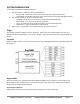
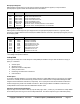
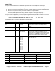
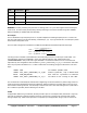
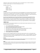
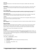
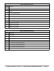
Table Of Contents
- FEATURES
- HARDWARE
- Pin Descriptions
- Hardware Connections
- Minimal Connections
- External Crystal
- Reset Switch
- SPI Flash Boot Memory
- MicroSD Boot Memory
- Dual Boot Memory
- OPERATION
- SYSTEM ORGANIZATION
- Cogs
- Cog RAM
- Register RAM
- Lookup RAM
- Execution
- Hub
- Hub RAM
- Cog-to-Hub RAM Interface
- System Clock
- CORDIC Solver
- Smart I/O Pins
- Pin Modes
- I/O Pin Circuit
- Equivalent Schematics
- Smart Modes
- PASM2 LANGUAGE IN BRIEF
- Math and Logic
- Pin & Smart Pin
- Branch
- Hub Control, FIFO, & RAM
- Event
- Interrupt
- Register Indirection
- CORDIC Solver
- Color Space Converter and Pixel Mixer
- Lookup Table, Streamer, and Misc
- SYSTEM CHARACTERISTICS
- Absolute Maximum Electrical Ratings
- DC Characteristics
- AC Characteristics
- PACKAGING
- CHANGE LOG
- PARALLAX INCORPORATED

System Clock
The system clock is the time base for all internal components and can be configured in several ways.
● Direct from internal slow clock (RCSLOW); a ~20 kHz oscillator is intended for low-power operation
● Direct from internal fast clock (RCFAST); a 20 MHz+ oscillator designed for minimum 20 MHz operation
● Direct from XI pin; driven externally via a clock oscillator or a crystal oscillator
● PLL-modified XI pin; driven externally via a clock oscillator or a crystal oscillator and the signal internally
modified by the PLL (phase-locked loop), usually to multiple to a much higher frequency
The system clock is configured by the running Propeller 2 application using the HUBSET instruction in this format:
HUBSET ##%0000_000E_DDDD_DDMM_MMMM_MMMM_PPPP_CCSS 'set clock mode
The bit fields (E, D, M, P, C, and S) are described in the following tables.
PLL Setting
Value
Effect
Notes
%E
0/1
PLL off/on
XI input must be enabled by %CC. Allow 10ms for
crystal+PLL to stabilize before switching over to PLL clock
source.
%DDDDDD
0..63
1..64 division of XI pin
frequency
This divided XI frequency feeds into the phase-frequency
comparator's 'reference' input.
%MMMMMMMMMM
0..1023
1..1024 division of
VCO frequency
This divided VCO frequency feeds into the
phase-frequency comparator's 'feedback' input. This
frequency division has the effect of multiplying the divided
XI frequency (per %DDDDDD) inside the VCO. The VCO
frequency should be kept within 100MHz to 350MHz.
%PPPP
0
1
2
3
4
5
6
7
8
9
10
11
12
13
14
15
VCO / 2
VCO / 4
VCO / 6
VCO / 8
VCO / 10
VCO / 12
VCO / 14
VCO / 16
VCO / 18
VCO / 20
VCO / 22
VCO / 24
VCO / 26
VCO / 28
VCO / 30
VCO / 1
This divided VCO frequency is selectable as the system
clock when SS = %11.
%CC
XI status
XO status
XI / XO impedance
XI / XO loading caps
%00
ignored
float
Hi-Z
OFF
%01
input
600-ohm drive
1M-ohm
OFF
%10
input
600-ohm drive
1M-ohm
15pF per pin
%11
input
600-ohm drive
1M-ohm
30pF per pin
Copyright © Parallax Inc. 2021/05/27 ▪ Parallax Propeller 2 (P2X8C4M64P) Datasheet ▪ Page 16