
Product Documentation
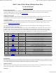

Mode Register
The mode register selects which mode of operation and I2C data input type the user requires. The options being:
0, (Default Setting) If a value of 0 is written to the mode register then the meaning of the speed registers is literal speeds in the
range of 0 (Full Reverse) 128 (Stop) 255 (Full Forward).
1, Mode 1 is similar to Mode 0, except that the speed registers are interpreted as signed values. The meaning of the speed registers
is literal speeds in the range of -128 (Full Reverse) 0 (Stop) 127 (Full Forward).
2, Writing a value of 2 to the mode register will make speed1 control both motors speed, and speed2 becomes the turn value.
Data is in the range of 0 (Full Reverse) 128 (Stop) 255 (Full Forward).
3, Mode 3 is similar to Mode 2, except that the speed registers are interpreted as signed values.
Data is in the range of -128 (Full Reverse) 0 (Stop) 127 (Full Forward)
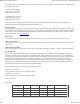
Command register
Command
Action
Dec Hex
32 20 Resets the encoder registers to zero
48 30 Disables automatic speed regulation
49 31 Enables automatic speed regulation (default)
50 32 Disables 2 second timeout of motors (Version 2 onwards only)
51 33 Enables 2 second timeout of motors when no I2C comms (default) (Version 2 onwards only)
160 A0 1st in sequence to change I2C address
170 AA 2nd in sequence to change I2C address
165 A5 3rd in sequence to change I2C address
Changing the I2C Bus Address
To change the I2C address of the MD25 by writing a new address you must have only one module on the bus. Write the 3 sequence
commands in the correct order followed by the address. Example; to change the address of an MD25 currently at 0xB0 (the default
shipped address) to 0xB4, write the following to address 0xB0; (0xA0, 0xAA, 0xA5, 0xB4 ). These commands must be sent in the
correct sequence to change the I2C address, additionally, no other command may be issued in the middle of the sequence. The
sequence must be sent to the command register at location 16, which means 4 separate write transactions on the I2C bus. Because of
the way the MD25 works internally, there MUST be a delay of at least 5mS between the writing of each of these 4 transactions.
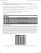
When done, you should label the MD25 with its address, however if you do forget, just power it up without sending any commands.
The MD25 will flash its address out on the green communication LED. One long flash followed by a number of shorter flashes
indicating its address. Any command sent to the MD25 during this period will still be received and writing new speeds or a write to
the command register will terminate the flashing.
Address
Long
Flash
Short
Flashes
Decimal Hex
176 B0 1 0
178 B2 1 1
180 B4 1 2
182 B6 1 3
184 B8 1 4
186 BA 1 5
188 BC 1 6
190 BE 1 7
Take care not to set more than one MD25 to the same address, there will be a bus collision and very unpredictable results.
MD23 Technical Documentation http://www.robot-electronics.co.uk/htm/md25i2c.htm
3 of 3 2013-05-31 10:26