
Product Documentation
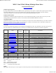

set the speed and direction of motor 1. The larger the number written to this register, the more power is applied to the motor. A mode
of 2 or 3 will control the speed and direction of both motors (subject to effect of turn register).
Speed2/Turn
When in mode 0 or 1 this operates the speed and direction of motor 2. When in mode 2 or 3 Speed2 becomes a Turn value, and is
combined with Speed1 to steer the device (see below).
Turn mode
Turn mode looks at the speed1 to decide if the direction is forward or reverse. Then it applies a subtraction or addition of the turn
value on either motor.
so if the direction is forward
motor speed1 = speed1 - turn
motor speed2 = speed1 + turn
else the direction is reverse so
motor speed1 = speed1 + turn
motor speed2 = speed1 - turn
If the either motor is not able to achieve the required speed for the turn (beyond the maximum output), then the other motor is
automatically changed by the program to meet the required difference.
GET ENCODER 1, GET ENCODER 2 or GET ENCODERS
When a read encoder command is issued the MD25 will send out 4 bytes high byte first, which should be put together to form a 32
bit signed number. For example a GET ENCODER 1 command may return 0x00,0x10,0x56,0x32.
So declare a 32 bit signed variable in your program, for C:
long result;
result = serin() << 24; // (0x00 shifted 24 bits left, effectively * 16777216)
result += serin() << 16; // (0x10 shifted 16 bits left, effectively * 65536)
result += serin() << 8; // (0x56 shifted 8 bits left, effectively * 256)
result += serin(); / (0x32)
result now equals 1070642 decimal or 0x105632 hex. If the highest bit was set then it would be -ve.
read encoders will send encoder count 1 and then encoder count 2 but is put together in exactly the same way. The registers can be
zeroed at any time by writing 0x35 to the MD25.
Battery volts
A reading of the voltage of the connected battery is available. It returns as 10 times the voltage (121 for 12.1v).
Motor 1 and 2 current
A guide reading of the average current through the motor is available. It reads approx ten times the number of Amps (25 at 2.5A).
Software Revision number
Responds with the revision number of the software in the modules PIC16F873 controller - currently 1 at the time of writing.
Acceleration Rate
If you require a controlled acceleration period for the attached motors to reach there ultimate speed, the MD25 has the ability to
provide this. It works by using a sent acceleration value and incrementing the power by that value. Changing between the current
speed of the motors and the new speed. So if the motors were traveling at full speed in the forward direction (255) and were
instructed to move at full speed in reverse (0), there would be 255 steps with an acceleration register value of 1, but 128 for a value
of 2. The default acceleration value is 5, meaning the speed is changed from full forward to full reverse in 1.25 seconds. The
WRITE ACCELERATION command will accept values of 1 up to 10 which equates to a period of only 0.65 seconds to travel from
full speed in one direction to full speed in the opposite direction.
So to calculate the time (in seconds) for the acceleration to complete :
if new speed > current speed
steps = (new speed - current speed) / acceleration register
MD25 Serial Documentation http://www.robot-electronics.co.uk/htm/md25ser.htm
2 of 3 2013-05-31 10:27