
Data Sheet
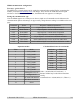
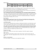

Temperature register
Register gives a reading of the current surface temperature of the PCB in degrees centigrade.
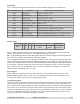
Motor current
This is the value used internally to limit the motor current to 20A. You do not need to read or do
anything with it. The value is proportional to motor current, with a value of 186 representing the 20A
limit.
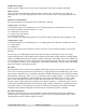
Software revision number
The revision number of the software in the modules PIC controller.
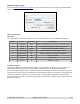
Analog mode – 0v-2.5v-5v
In this mode the motor is controlled by a 0v to 5v analog signal only on the SDA line. Pin SCL is
unused and should be connected to either +5v or 0v.
0v is maximum reverse power
2.5v is the center stop position
5v is full forward power
The is a small (2.7%) dead band around 2.5v to provide a stable off position, input impedance is 47k.
Analog mode – 0v-5v
In this mode the motor is controlled by a 0v to 5v analog signal on the SDA line and direction on SCL.
0v is stop position
5v is full power
Pin SCL is the logic level (ttl) direction control. logic 0 for reverse direction and logic 1 for forward
direction.
You may also use a PWM signal instead of an analog voltage on the SDA line. There is a simple
resistor/capacitor filter on the module which will generate the analog voltage from the incoming PWM
signal. your PWM signal should be 20khz or greater in frequency and ideally, come from a CMOS gate
(0-5v) rather than ttl (0-3.5v ish). a 0% duty cycle will represent 0v and a 100% duty cycle representing
5v. This applies to both the above analog modes. Note that the PWM input is not the same as the PWM
motor drive which is generated seperately.
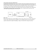
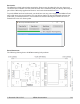
RC mode
This mode allows direct connection to standard model radio control receivers. Most receivers work
from a 4.8v-6v battery pack and can be powered by 5v supply that powers the MD04 logic. The control
pulse (Yellow) from the receiver should be connected to the SDA terminal. The SCL terminal is unused
and should be connected to either +5v or 0v. Connect the receiver supply (Red) to +5v logic supply and
the receiver 0v ground (Black) to the MD04 logic ground. The output from an RC receiver is a high
pulse 1.5mS wide when the joystick is central. This varies down to 1.1mS and up to 1.9mS as the
joystick is moved. This range can be shifted by the centering control by +/-100uS from 1mS-1.8mS to
1.2mS-2mS. The MD04 provides full control in the range 1.1mS to 1.9mS with 1.5mS being the center
off position. There is a 7uS dead zone centered on 1.5mS for the off position. The Radio Transmitter
centering control should be adjusted so that the motor is off when the joystick is released.
RC mode with timeout
Operates in much the same way as the normal RC control with the difference being the addition of a
timeout feature. If a RC pulse is not detected for a period in excess of 200ms, then the motor will be
stop being driven until a valid RC signal is received
© Devantech Ltd 12/07/15 MD04 documentation 7/8