
Datasheet

www.robot
-electronics.co.uk LCD05 datasheet 1.0
Page 5 of 6 Devant
ech Ltd, Mar 2013
Contrast and brightness set
C
ontrast and brightness may be adjusted using software commands to vary the level between 0 and 255. Following a power cycle the LCD05
will automatically revert to a predetermined level for the display that is attached.
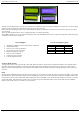
Changing display type
Because there are four variations of the LCD display that the LCD05 connects to a software command can be used to switch between them.
Firstly a command of 24 must be issued, this is then followed by the display type attached:
LCD style Byte
20 x 4 Green 3
20 x 4 Blue 4
16 x 2 Green 5
16 x 2 Blue 6
Custom char generator
Custom characters can be generated by sending an 8 byte map. The first thing that must be done is to send a command of 27 to indicate that
you intend to make a custom char. Next you have to specify the position in ram of one of the 8 available chars you intend to build, the 8
chars are mapped at positions 128-135. Then the pattern should be sent as below.
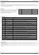
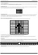
How to calculate an 8 byte character pattern:
8 bytes are sent with the high bit masked on, the next two are ignored (x) and the final 5 bits show the line pattern.
Bit
4
Bit
3
Bit
2
Bit
1
Bit
0
Sent
byte
Byte 0 1xx00000 (128)
Byte 1
1xx00100 (132)
Byte 2
1xx01110 (142)
Byte 3 1xx10101 (149)
Byte 4
1xx00100 (132)
Byte 5
1xx00100 (132)
Byte 6
1xx00100 (132)
Byte 7 1xx00000 (128)
So t
o build the above arrow into location 128 you would send this sequence to the command register:
27 (char generate command),128 (location to be filled),128,132,142,149,132,132,132,128
Now the char is built into a memory location it can be called at any time as long as the module remains powered by simply sending the
address between 128 and 135.
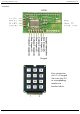
Keypad input
An added feature of the module is the ability to connect a 3 x 4 Keypad, the module will automatically scan the status of the keys at regular
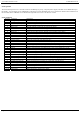
intervals. The result is then provided in two bytes for easy use, shown by the diagram below. Each bit represents the row and column of each
button on the keypad. The second row is the keypad characters when using our keypad.
High byte Low byte
0 0 0 0 4/3 4/2 4/1 3/3 3/2 3/1 2/3 2/2 2/1 1/3 1/2 1/1
# 0 * 9 8 7 6 5 4 3 2 1
Any key press will result in the corresponding bit in the byte being driven high. In I2C m
ode these bytes are available for reading from
registers one and two.
In serial mode, just send 16 to the LCD05 and it will reply with the two bytes as above with the low byte first.