
Datasheet

www.robot
-electronics.co.uk LCD05 datasheet 1.0
Page 3 of 6 Devant
ech Ltd, Mar 2013
I2C operati
on
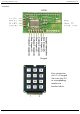
The I2C display is at an address of 0XC6. The SCL and SDA lines should have pull-up resistors on on the bus. You only require 1 pair of
resistors for the whole I2C bus, not specifically for the LCD05. They are normally on the master controller and you may already have them.
Anything between 1k8 and 10k should work.
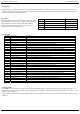
I2C commands
Decimal Command Description
0 null (ignored) Ignored as a no operation
1 Cursor home Sets the cursor to the home position (top left)
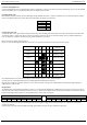
2 Set cursor (1-80/32) Set cursor using the next byte, where 1 is the top left and 80/32 is the bottom right
3 set cursor (row, column) Sets cursor using two bytes, where first byte is the row and the second byte is the column
4 Hide cursor Stops the position cursor from appearing on the display
5 Show underline cursor Changes the cursor to the underline type
6 Show blinking cursor Changes the cursor to the blinking type
8 Backspace Deletes the preceding character from the current position on the display
9 Horizontal tab (by tab set) Moves the cursor position to next tab point set by command 18 (default tab space 4)
10 Smart line feed Moves the cursor down one line to the position beneath in the same column
11 Vertical tab Moves the cursor up one line to the position above in the same column
12 Clear screen Clears the screen and sets cursor to the home position
13 Carriage return Moves the cursor to the start of the next line
17 Clear column Clears the contents of the current column and moves cursor right by one column
18 Tab set Sets the required tab size, the following byte can be a size of between 1 and 10
19 Backlight on Turns the backlight of the LCD05 on
20 Backlight off (default) Turns the backlight of the LCD05 off
21 Disable start-up message Disables the display of setup information at power up
22 Enable start-up message Enables the display of setup information at power up
23 Save as start-up screen Saves current screen and displays it on power up
24 Set display type Sets which display is connected to the LCD05 (see changing display type below)
25 Change address First byte of sequence to change LCD05 address (see changing address below)
27 Custom char generator Allows 8 custom chars to be built. See custom char generator section
28 Double keypad scan rate Increases the frequency of the keypad scan to 20hz
29 Normal keypad scan rate Returns to the default keypad scan frequency of 10hz
30 Contrast set Byte following this command will be contrast level (0-255)
31 Brightness set Byte following this command will be brightness level (0-255)
32-255 ASCII chars Writes ASCII chars straight to the display
Changi
ng address
The LCD05 software contains the facility to easily change the modules address on the I2C bus system in the range of 0xC6 - 0xCE ( even
numbers only ). This is achieved by sending the following sequence: 0x19,0xA0,0xAA,0xA5 then 0xC6, 0xC8,0xCA,0xCC or 0xCE ( new
address to map LCD05 at )
Current address is displayed every time the module is first powered as a default, this may be changed to no display or custom display by user
command.
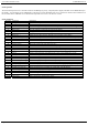
I2C registers
The LCD05 has four registers, three being read only information
registers. Register 0 is a dual purpose register, when written it is
the command register where all of the instructions from the
commands section should be sent, when read it returns the
number of free bytes in the FIFO buffer.
Register Read Write
0 Number of free bytes in FIFO buffer Command register
1 Keypad state Low byte x
2 Keypad state High byte x
3 Version x