
Data Sheet

5
Sheet No. : OP13003EN
GP2Y0E02A
■Notes
[Advice for the optics]
●Lens of this device shall be kept cleanly. There are cases that dust, water or oil and so on deteriorate the characteristics
of this device. Please consider in actual application.
●In case that protection cover is set in front of this sensor , the protection cover shall be recommended to use material
which doesn’t scatter light and be matt finish. And the protection cover which has the most efficient transmittance
at the emitting wavelength range of LED for this product (λ=850nm±70nm). And this protection cover is recommend to
be flat. And this protection cover shall be recommended to be parallel to the emitter and detector portion. In case that
protection cover is set in front of this sensor, It emits reflected light from this protection cover. If this reflect light reaches
in detector portion, the output distance of this product may be changed. The output distance characteristics of this product
may be changed with according to material (①) or transmittance (②) or the thickness (③) or the distance
between the protection cover and this product (④) or the angle between surface and back (⑤) or the angle between this
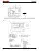
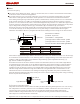
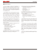
cover and this sensor(⑥). In case that protection cover is set, please design to consider that this reflective light is
minimized. And it shall be effective to put light shield wall between emitting lens and receiving lens as shown in below.
Sensor
③thickness
Protection cover
④Distance
Fixed reference conditions :
①material : acrylic resin
②transmittance : >90%@850nm
⑤the angle between surface and back : parallel
⑥the angle between cover and sensor : parallel
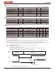
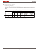
Condition
No1
No4
No3
No2
③thickness
1mm
2mm
2mm
1mm
④distance
0mm
1mm
0mm
1mm
light shield wall
-
exisitence【*】
-
nonexistence
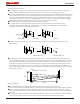
Cover has the surface finish without light diffusion.
Direct reflective light becomes large as Distance from sensor to protection cover and thickness of this cover become large.
In case thickness is 2mm and distance is 1mm, measuring distance is changed shift larger from actual distance than other
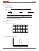
condition. It shifts can make small by using installation of light shield【*】and compensation function【**】.
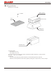
Inner distance between lens of detector and lens of emitter is around 0.6mm (reference). So the width of light shield is
recommended to be less than 0.6mm. In case the width of light shield is longer than inner distance, measuring distance
is changed by Shield a part of emitter lens or detector lens. Please confirm that there is no problem under the actual
equipment. And In case between protection cover and light shield or between light shield and this sensor exists space,
The effect of light shield is small because light from emitter leaks. The light shield wall is recommended to use the
material that have the low transmittance at the emitting wavelength range of LED for this product (λ=850nm±70nm).
When the material of light shield wall is hard, and the power stress in which it is added to this product is large, measuring
distance may shift from actual distance.
【*】Noted for installation of light shield
Light shield wall
Protection
cover
Light shield wall
The width of
light shield wall
【**】Noted of compensation function
This product has the function which rectifies error shift by the direct reflective light from protection cover. The accuracy
after compensation is based on a protection cover or its installation condition. This function can be active when it set
correction factor in this product by E-fuse. Please refer to application manual about the detail of this function.
Neither installation of a light shield wall nor use of a compensation function guarantees the distance characteristic.
These improve error shift of the distance characteristic.
Regardless of use of a light shield wall or a compensation function, please use it after confirming with customer’s product.