
Technical Document
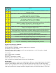

Command
Action
dec hex
16 10
Get Module Info - returns 3 bytes. Module Id (21 for ETH8020), Hardware version,
Firmware version.
32 20
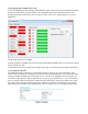
Digital Active - follow with 1-20 to set relay on, then a time for pulsed output from 1-255
(100ms resolution) or 0 for permanent
Board will return 0 for success, 1 for failure
33 21
Digital Inactive - follow with 1-20 to turn relay off, then a time for pulsed output from 1-
255 (100ms resolution) or 0 for permanent
Board will return 0 for success, 1 for failure
35 23
Digital Set Outputs-follow with 3 bytes, first byte will set relays 1-8, All on = 255 (0xFF),
All off = 0, 2nd byte for relays 9-16, 3rd byte for relays 17-20
Board will return 0 for success, 1 for failure
36 24
Digital Get Outputs- returns3 bytes, the first corresponds with relays 1-8, 2nd byte for
relays 9-16, 3rd byte for relays 17-20
37 25
Digital Get Inputs- returns4 bytes, the first three bytes are always 0, the 4th bytes bits
correspond with the 8 digital inputs, a high bit meaning input is active (driven low)
50 32
Get Analogue Voltage - follow with 1-8 for channel and ETH8020 will respond with 2
bytes to form an 16-bit integer (high byte first)
119 77 Get Serial Number - Returns the unique 6 byte MAC address of the module.
120 78 Get Volts - returns relay supply voltage as byte, 125 being 12.5V DC
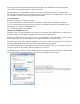
121 79 Password Entry - see TCP/IP password
122 7A Get Unlock Time - see section below
123 7B Log Out - immediately re-enables TCP/IP password protection
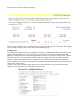
Digital Active/Inactive Commands
These are 3 byte commands:
The first byte is the command, 32 (active means on) or 33 (inactive).
Second byte is the relay number.
Third byte is the on time. Set this to zero for un-timed operation, or 1-255 for a pulse in 100mS
intervals (100mS to 25.5 seconds).
For example:
0x20 - turn the relay on command
0x03 - relay 3
0x32 (50) - 5 seconds (50 * 100ms)
Board will return 0 for success, 1 for failure
Note - All bytes in a command must be sent in one TCP/IP packet.
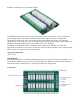
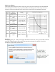
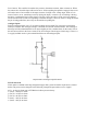
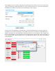
Digital inputs
The 8 analogue inputs are used to create 8 digital inputs. When you request digital inputs a threshold is
applied to the 8 analogue inputs. Above 3v will read as low (inactive), below 2v will read as high
(active). The region from 2v to 3v is the hysteresis and does not change the previous reading. There are
weak pull-up resistors on the inputs which are designed to allow you to directly connect a VFC (Volt