
User Manual
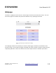
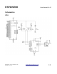
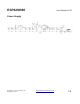
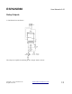
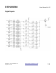
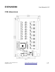
Table Of Contents
- Overview
- Control Protocols
- WiFi
- Configuration
- USB Configuration Commands
- ST Status. Return the system status
- RB ReBoot.
- IP Sets the modules IP address.
- SB Sets the SuBnet mask.
- GW Sets the GateWay address.
- PD Sets the Primary DNS.
- SD Sets the Secondary DNS.
- SS This sets the SSID.
- PW Sets your networks WIFI password.
- PA Sets the TCP/IP port number for the ASCII commands.
- MS Sets the MQTT broker address
- MD Sets the MQTT ID for this module
- MP Sets the MQTT broker’s port.
- R1-R8 Sets the MQTT topic this relay is subscribed to.
- N1-N8 Sets the MQTT topic this Input will publish to.
- TCP/IP Commands.
- HTML Commands.
- Webpage
- Schematics
- PCB dimensions
- Notes

ESP32SR88 User Manual v1.00
HTML Commands.
There are a set of HTML commands that can be used to control the module.
?Rly3=1 This will turn on relay 3
?Rly3=0 This will turn off relay 3
?Rly3=2 This will toggle relay 3 to the opposite state.
You can enter the commands into a browser immediately after the IP address.
http://192.168.0.3/?Rly3=1
This will turn on relay 3.
In response the module will return an XML file, which your browser will display.
<?xml version="1.0" encoding="UTF-8"?>
<ESP32SR88DATA>
<RELAYS>
<RLY1>off</RLY1>
<RLY2>off</RLY2>
<RLY3>on</RLY3>
<RLY4>off</RLY4>
<RLY5>off</RLY5>
<RLY6>off</RLY6>
<RLY7>off</RLY7>
<RLY8>off</RLY8>
</RELAYS>
<INPUTS>
<INP1>1</INP1>
<INP2>1</INP2>
<INP3>1</INP3>
<INP4>1</INP4>
<INP5>1</INP5>
<INP6>0</INP6>
<INP7>1</INP7>
<INP8>1</INP8>
</INPUTS>
</ESP32SR88DATA>
The XML file is generated after the command has executed, therefore will reflect the new status of
the relays.
Copyright © 2020, Devantech Ltd.
All rights reserved.
www.robot-electronics.co.uk
11