dS1242 User Manual v4.03 dS1242 User Manual Version 4.03 Copyright © 2016-2018, Devantech Ltd. All rights reserved. www.robot-electronics.co.
dS1242 User Manual v4.03 Table of Contents Documentation history.......................................................................................................................... 3 A quick look........................................................................................................................................ 4 Introduction........................................................................................................................................ 5 Getting started....
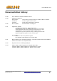
dS1242 User Manual v4.03 Documentation history V2.18 First release of separate dS1242 manual V2.19 Added new features: Peer to Peer Use events to control relays on another dSxxxx module. Schedules Create regular timed events Counters Count input transitions or seconds V2.20 Minor update v3.01 Application update Documentation unchanged. Added ModBus function 15, Write Multiple Coils. Increased to 32 relays. On dS3484, relays 5-32 are virtual relays.
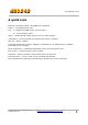
dS1242 User Manual v4.03 A quick look Ethernet connected module, 10/100Mb auto negotiated. Relays – 2 x 16Amp 250Vac C/O. I/O – 4 x digital I/O's NPN output, Volt free input. 2 x 10-bit analogue input Power – 12VDC 500mA supply required. 2.1mm center positive. Connections – Screw Terminals for N/O N/C and Common contacts PCB size – 82mm x 84mm Controlled graphically by secure webpage or optionally one of ASCII, Binary or Modbus command sets over TCP/IP.
dS1242 User Manual v4.03 Introduction The dS1242 is an Ethernet connected relay module featuring 2 channels of 16Amp 250Vac relays. Each relay has both normally open (NO) and normally closed (NC) as well as the common available on three terminals. In addition to the relays, the dS1242 has 4 digital I/O channels and 2 x 10-bit analogue input channels (0v-3.3v input range). The dS1242 requires a 12v power supply capable of supplying a minimum of 500mA such as this one: http://www.robot-electronics.co.
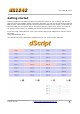
dS1242 User Manual v4.03 Getting started Start by plugging in the Ethernet cable to connect the module to your network, and the 12v jack plug from your adapter. Switch on and the first thing you will note is that the blue LED will flash 3 times. This indicates that the control firmware is loaded on the module. (If the blue led does not flash you will need to load in the control firmware. Don't worry, this is very easy to do.
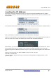
dS1242 User Manual v4.03 Locating the IP Address If you are not using a windows PC then you will need to find the IP address of the module. The simplest method is connect the module (Ethernet, USB then lastly, Power) and load up the dScript editor. Go to Module→Select Port and make sure the correct serial port is selected as illustrated above. Now go to Module→ IP Address and the current IP address is displayed. Make sure the Ethernet is connected before you apply power.
dS1242 User Manual v4.03 If you prefer, you can download a java program that will run on Windows, MAC or Linux, and will list all of our modules that are connected to your LAN. DevantechModuleFinder.jar If you do not have a DHCP server the dS1242 will use a default IP address of 192.168.0.123 so make sure your PC is on the same subnet of 255.255.255.0 and its IP address is 192.168.0.xxx Copyright © 2016-2018, Devantech Ltd. All rights reserved. www.robot-electronics.co.
dS1242 User Manual v4.03 Configuring the dS1242 There are a set of configuration pages to get the dS1242 operating as you want it. These pages are all _configx.htm, (that's a leading underscore character). ie. _config.htm _config2.htm Anything that starts with _config is considered a special name for configuration pages and can only be seen if you have the the USB cable plugged in and connected to your PC. Why only if the USB cable is plugged in? Its an additional security measure.
dS1242 User Manual v4.03 Status page You should now see the following page: This status page shows you the system firmware revision as well as the supplied voltage to the board and its internal temperature. If you hover your mouse cursor over the menu buttons on the left, the help panel will give you an overview of each one. Copyright © 2016-2018, Devantech Ltd. All rights reserved. www.robot-electronics.co.
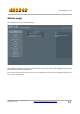
dS1242 User Manual v4.03 Network page Notice that everything below the Host Name is greyed out and can't be changed. This is because the “Enable DHCP” box is checked and all the greyed out fields are supplied by the DHCP server. Although a quick way to get you connected, we really do not recommend this as the DHCP server can assign a different IP each time you power up.
dS1242 User Manual v4.03 TCP/IP page The TCP/IP tab allows you to select one of three command sets to control the module. These are independent of, and separate to the HTML webpage control. Clicking on one of the four check boxes will select that command set. Only one command set may be selected. You can disable all TCP/IP command sets by clicking on an already selected box. The ASCII command set is text based. You can use any program that can send text over TCP/IP. We use PuTTY in raw mode.
dS1242 User Manual v4.03 Webpage security Allows you to prevent unauthorised personnel from accessing the application webpage or using it to control the module. Leaving the Security Password blank will disable it and allow everyone to access the application page to control the module. To enable password protection enter a password into the Password box. You can use any characters from the ASCII character set from 0x20 to 0x7E except “ (0x22).
dS1242 User Manual v4.03 You will see something like this: The password is now loaded on your browser. Do the same for any further browsers you want to enable. When you have done uncheck the “Enable _pw.htm” box to prevent anyone else from loading the password. When the “Update Pending” light goes out re-boot the module again. The default port used by html webpages is 80. You can change this if required. If you do so then you will need to include the port number in the address.
dS1242 User Manual v4.03 Configuring relays The Relays tab allow you to set the names of the 32 relays that will be displayed on the application page. Use the Relay No. box to select the relay to configure. There are 32 relays available. Relays 1 & 2 are the physical relays on the module. Relays 3-32 are virtual relays, they have no physical presence but otherwise behave the same as the real ones.
dS1242 User Manual v4.03 Relay automation If you are going to be controlling the relays from the web-page or using one of the ASCII, Binary or Modbus command sets, then you do not need to do anything here. Just leave the automation fields blank. Relay No. box This selects the relay you wish to configure. There are 32 relays available. The first 2 relays are the actual relays on the module. Relays 3-32 are virtual relays. They have no physical presence but otherwise behave identically to the real ones.
dS1242 User Manual v4.03 Here's a very simple example: Enter R2 into the Relay 1 Pulse/Follow box. This will make relay 1 copy whatever you do to Relay 2. Try it! Now change it to !R1. The exclamation mark is read as “Not R1”. Now relay 1 will always be the opposite of relay 2. Try it. Boolean equations may be used for controlling relays and other objects such as email. See the “Boolean equation” section later in this manual for full documentation. Copyright © 2016-2018, Devantech Ltd.
dS1242 User Manual v4.03 Set Reset & Toggle boxes When used, these three controls contain boolean equations. The “Set Relay” box will set the relay when the boolean equation becomes true. The other two boxes reset and toggle the relay when the boolean equation become true. This is important! The Set, Reset and Toggle controls are transitory (edge triggered) controls. The relays are only affected at the moment the boolean equation becomes true.
dS1242 User Manual v4.03 Naming I/O's The Input/Output tab is used to assign meaningful names to the I/O terminals. As with relay names these may be up to 20 characters long, but do check it looks ok on a mobile device or whatever you are using to control the module. Connecting I/O to Virtual Relays Any of the four digital I/O lines may be connected to a virtual relay. This gives the digital output the same automation capabilities as the relays. Enter the relay number in the link box as shown above.
dS1242 User Manual v4.03 Email notifications The Email tab is for sending secure, AES encrypted email notifications from the module. Up to eight (8) email notifications may be set up, selected with the Email No. box. Setting up emails is quick and easy. You just need the recipients email address, a notification message which will be the email subject line and the trigger event. The “from” address is common to all eight emails.
dS1242 User Manual v4.03 Peer to Peer This tab allows you to configure events on this module to control relays on another. Up to eight (8) Peer to Peer events may be set up, selected with the P2P No. box. Control of the target relay is by using the binary command set only. This can optionally use AES encryption. The Target module must be set to either Binary or AES Binary mode on its TCP/IP tab, and this “Use AES” checkbox set to match.
dS1242 User Manual v4.03 Schedules The scheduler can schedule regular events. These can be once or twice daily with the two start and stop times and can happen on any selected weekdays. The Schedule No. is one of eight schedules that can be set up. These are selected with the Schedule No. box. The target relay is the local relay that you want this schedule to control. W/Days selects the days of the week you want this schedule to control the relay. When highlighted in red, the weekday is active.
dS1242 User Manual v4.03 The timezone allows you to set the time for your location. For example; GMT leave this at 0. CET set this to 1. PST set this to -8 IST set this to 5:30 Daylight saving time may be checked if required. It advances the time by 1 hour between the last Sunday in March and the last Sunday in October. As well as controlling a relay directly, schedules may also be used in the boolean equation fields of other controls.
dS1242 User Manual v4.03 Counter/Timers Count input pulses or time events. There are a total of eight counter/timers available, selected with Counter No. box. Each counter can count at a maximum speed of 20Hz (20 counts per second). Counter Name Each counter/timer may be named and this name appears on the application page and email notifications. Count Input Each counter/timer is capable of being a timer by entering T1 into its count input box.
dS1242 User Manual v4.03 Reset Input This input will reset the counter value to zero. If the capture Input has been left blank then it will store the current counter value in the capture register before resetting it to zero. You may use an input such as D3 or you can use the counter value itself. Entering C1>9 for the counter1 Reset Input will reset the counter when it reaches 10. This will create a repeating 10 step timer (0-9). Counters, Timers and Schedules can be combined.
dS1242 User Manual v4.03 The internal time base, T1 is derived from the crystal on the module. It’s accurate but will drift over time so that the capture event may not happen “on the hour”. Even if you started it on the hour is will drift out by a few seconds a day. So as a final refinement we will synchronize our time base with the real time derived from a schedule. The target relay is set to zero as we don’t need to use any relays for this.
dS1242 User Manual v4.03 The application page The last tab in the configuration pages takes you directly to the application page so you can quickly see the results of your configuration changes. The I/O indicators show grey when the I/O is inactive. Red indicates an active input/output. The I/O's are clickable just like the relay buttons to turn them on and off. The screen shows the first four of the eight available counters and their capture registers. Copyright © 2016-2018, Devantech Ltd.
dS1242 User Manual v4.03 This application page is “index.htm” and is located in the webpage directory: /dScriptPublish-4-03/Examples/app-dS3484-v4-03/webpage/ You can use any html/javascript editor to change this file to your own requirements, such as adding a company logo or removing unused relay buttons. Application page security The configuration pages (any page name starting with _config) are only served when the USB port is connected.
dS1242 User Manual v4.03 Accessing your webpage from the internet Now you have your webpage up and running on your local network, for example 192.168.0.150, and you can access the webpage and control the module. You just go to 192.168.0.150/index.htm, and the page is there. However you can't get directly at that page from your phone when you are away from home. You can't access it on 192.168.0.150 because your network is not publicly accessible, its a private network address.
dS1242 User Manual v4.03 Boolean equations Boolean equations are used in a number of places in the configuration screens. They are used for relay automation, triggering emails and peer to peer events and the count, capture and reset for the counter/timers. The types that can be used in boolean equations are: 1. Relays, R1 – R2 2. Digital I/O's, D1 – D4 3. Analog inputs, A1 – A2 4. Schedules, S1 – S8 5. Counters, C1 – C8 6. 1Hz Time base, T1 The simplest equation is R1.
dS1242 User Manual v4.03 To demonstrate a real world example, take the analog example above where we compared A1 with 1000 to operate R2. Whilst this would work its a not a good solution as the relay would jitter badly when A1 was hovering between 999 and 1000. What we need is some hysteresis. To do that we will use R2 in its own equation. (A1<1000&!R2)|(A1<1234&R2) Assume R2 in inactive (off). The 2nd half of the equation (A1<1234&R2) will have no effect. So when A1 falls below 1000 the relay comes on.
dS1242 User Manual v4.03 TCP/IP command sets There are four TCP/IP command sets on four selectable check boxes, of which one or none may be selected on the TCP/IP config tab. These are ASCII, Modbus, Binary and Binary with AES256 encryption. ASCII command set The ASCII command set allows you to type commands using a TCP/IP terminal program such as PuTTY. Use PuTTy in raw mode.
dS1242 User Manual v4.
dS1242 User Manual v4.03 Binary command set Summary. 0x30 Get Status 0x31 Set relay 0x32 Set output 0x33 Get Relays 0x34 Get Inputs 0x35 Get Analogue 0x36 Get Counters 0x30 (decimal 48) Get Status (1 byte command, returning 8 bytes) This command returns 8 bytes of status data Module ID This will be 31 (0x1F) for the dS1242 System Firmware Major 2 for example System Firmware Minor 18 for example Application Firmware Major 1 for example Application Firmware Minor 2 for example Volts Power supply volts x 10.
dS1242 User Manual v4.03 0x32 0x04 0x01 Set Output (3 byte command, returning 1 byte) This command turns an output on or off and returns an ACK/NACK byte. ACK=0, NACK=nonzero (actually the unknown I/O port number). All I/O's which need to be inputs should have the output turned off. When turned on the NPN transistor can sink up to 100mA. 0x32 The command, the rest are parameters 0x04 the I/O number, 4 in this case.
dS1242 User Manual v4.03 Binary Command Set – continued. 0x35 Get Analogue inputs (1 byte command returning 4 bytes) This returns all 2 possible analogue inputs. 4 bytes are returned, 2 for each analogue input. Byte 1 0x02 byte 2 0x3E for example: combined to 0x023E, or 574 decimal for input 1. Byte 3 0x01 byte 4 0xFB combined to 0x01FB, or 507 decimal for input 2. 0x36 0x01 Get Counters (2 byte command – returning 8 bytes) This command is used to get the counters.
dS1242 User Manual v4.03 Commands with generate and send you a Nounce are: 0x30 – Get Status 0x31 – Set Relay 0x32 – Set Output Commands which require a Nounce to be sent by you are: 0x31 – Set Relay 0x32 – Set Output A Nounce is only ever used once, you must always used the most recently issued Nounce. The following example shows how the Nounce provided by the module is used in the next Set Relay or Set Ouput command.
dS1242 User Manual v4.03 Modbus commands The modbus command set accepts a subset of the standard Modbus-TCP frames as defined in Modbus protocol Specification and MODBUS Messaging on TCP/IP Implementation Guide V1.0b Functions 1, 4, 5 & 15 are supported along with error codes 1, 2 & 3 should they occur. The UI (Unit Identifier) should be 0x01 to access this module. Function 01 (0x01) Read Coils This function reads back the 2 relays as coils 1-2 and also the 4 inputs as coils 41-44.
dS1242 User Manual v4.03 Function 05 (0x05) Write Single Coil This function is used to write to a single coil (relay or I/O). Coils 1-2 are the relays 1-2. Coils 41-44 are the I/O's 1-4 remapped to coils 41-44. Function 15 (0x0F) Write Multiple Coils Use this function when you need to write to multiple relays and I/O’s at the same time. Coils 1-2 are the relays 1-2. Coils 41-44 are the I/O's 1-4 remapped to coils 41-44.
dS1242 User Manual v4.03 Loading the application firmware If your module does not flash the blue LED three times on power-up, you will need to update the system firmware and load the application program. These instructions should also be followed if you want to update your firmware to the latest version or even revert to an earlier version. You need to download the dScript programming environment from here: http://www.robot-electronics.co.uk/dscript.
dS1242 User Manual v4.03 5. Run the dScript editor. Look in Help→About and check you have the latest version of dScript. In this case 4.03 If you have an earlier version you should uninstall it and install the new version from the installation folder, then start these instructions from the beginning. Older versions will not work with the new application. 6. Now look in the Module panel, you should see: v1.01 indicates it’s the boot-loader that is running. 7. Load the project: File→Open project \dScript
dS1242 User Manual v4.03 Erasing old configuration settings Uploading the firmware, as described in the previous section, will not erase all the configuration values. If you need to clear these, do the following: Load up the app-dS1242-v4-03 application in the editor, but before you upload it to the dS1242 you need to make a small change. Locate the thread "main" (click the word in the right panel is quickest). Just below this is a commented out line "init()". Uncomment this by removing the semicolon.
dS1242 User Manual v4.03 dS1242 Hardware The dS1242 provides two (2) volt free contact relay outputs with a current rating of up to 16Amp each, 4 digital I/O's which can be an NPN transistor output or accept a volt free input (from relay or switch contacts, etc). 2 analogue inputs (0-3.3v level) and 1 serial port (3.3v level). The module is powered from a 12vdc supply which can be regulated or unregulated. The relays are SPCO (Single Pole Change Over) types.
dS1242 User Manual v4.03 LED indication The dS1242 provides a red LED mounted immediately next to each relay to indicate whether it is in a powered state (LED on), there are also two LED's mounted in the Ethernet connector which will flash with Ethernet traffic. A row of three LEDs, Blue, Green and Red, are available to the user for status indication. The Red LED lights when the module is in bootloader mode – this is when the IDE is uploading system firmware to the module.
dS1242 User Manual v4.03 Power relays Four 16A volt free contact relays are provided for switching a common input between a normally closed output and a normally open output. The relay coil is powered by the 12vdc incoming supply on user command. Coil C Relay in passive state NC Coil NO C Relay in powered state NC NO A full datasheet for the relays used on the dS1242 is here: HF115FD datasheet Copyright © 2016-2018, Devantech Ltd. All rights reserved. www.robot-electronics.co.
dS1242 User Manual v4.03 Digital IO Our Ethernet modules could potentially have many types of outputs. For example the ETH008 only has one type - Relays. The dS1242 has both Relay outputs and NPN Open Collector Transistor outputs. Activating a relay means turning the relay on. Likewise activating an output means turning the transistor on. This will cause it to sink current to 0v ground. If you had an LED connected from the output to 12v (via a resistor of course) it would light up.
dS1242 User Manual v4.03 Connection Examples Example input - connecting a switch Connecting a simple switch could not be easier, just wire the switch between a pin (P) and ground (G). When the switch closes the input will become active. Example output - connect a relay You can connect your own 12V relays, the first coil pin of the relay is wired to the 12V supply terminals on the board, the other is wired to the output pin (P).
dS1242 User Manual v4.03 Analogue inputs Four independent analogue input channels are provided for sampling voltages up to 3.3V. Each channel is also filtered with a 10k resistor and a 100n capacitor to stabilise high frequency jitter, there is also a pull down resistor so the port will read around 0 when nothing is connected. 5V inputs can be used, although the 3.3V to 5V region will merely read full scale.
dS1242 User Manual v4.03 Serial Port Connections TTL serial ports. The dS1242 has one serial port header. Pin 1 is marked on the PCB. Tx and Rx operates at 3.3v levels, however the Rx input is 5v tolerant. Most 5v TTL level serial ports will accept a full 3.3v input ensuring the port is compatible with most 5v devices such as the LCD05 display modules. That is the reason 5v (rather than 3.3v) is available on pin1 to power external modules. Copyright © 2016-2018, Devantech Ltd. All rights reserved. www.
dS1242 User Manual v4.03 dS1242 dimensions Copyright © 2016-2018, Devantech Ltd. All rights reserved. www.robot-electronics.co.
dS1242 User Manual v4.03 Notes Copyright © 2016-2018, Devantech Ltd. All rights reserved. www.robot-electronics.co.