
Data Sheet

CMPS14 – documentation
Introduction
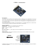
The CMPS14 is our 5th generation tilt compensated compass. Employing a 3-axis magnetometer, a 3-axis gyro
and a 3-axis accelerometer. At the core of the module is the superb BNO080 running algorithms to remove the
errors caused by tilting of the PCB. The module also allows the calibration to be stopped and instead rely on a
static calibration profile.
Power supply requirements are flexible, you can feed between 3.3 - 5v and the module draws a nominal 18mA
of current. A choice of serial or I2C interfaces can be used for communication.
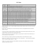
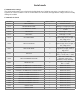
Overview of outputs
Heading, 16 bit – 2 outputs, one calculated by Bosch and one by us
Heading, 8 bit – 0-255 scaled for simpler requirements
Pitch – +/- 0-90° or +/- 0-180°
Roll – +/- 0-90°
Raw sensor outputs – 3 x 16 bit integers for each of the Magnetometer, accelerometer and gyro
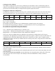
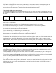
Mode selection
Serial or I2C mode is easily selected with the state of the mode pin. Note the CMPS14 looks at the mode
selection pin at power-up only.
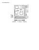
3.3v-5v
SDA/TX
SCL/RX
Mode
Factory use
0v ground
For I2C the mode pin can be left open or pulled to the supply voltage, for serial mode the mode pin should be
connected to 0v ground.