
Data Sheet
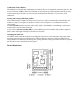

I2C Mode
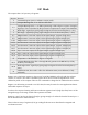
The compass has a 31 byte array of registers:
Register Function
0 Command register (write) / Software version (read)
1 Compass Bearing 8 bit, i.e. 0-255 for a full circle
2,3
Compass Bearing 16 bit, i.e. 0-3599, representing 0-359.9 degrees. register 2 being the
high byte. This is calculated by the processor from quaternion outputs of the BNO055
4 Pitch angle - signed byte giving angle in degrees from the horizontal plane (+/- 90°)
5 Roll angle - signed byte giving angle in degrees from the horizontal plane (+/- 90°)
6,7 Magnetometer X axis raw output, 16 bit signed integer (register 6 high byte)
8,9 Magnetometer Y axis raw output, 16 bit signed integer (register 8 high byte)
10,11 Magnetometer Z axis raw output, 16 bit signed integer (register 10 high byte)
12,13 Accelerometer X axis raw output, 16 bit signed integer (register 12 high byte)
14,15 Accelerometer Y axis raw output, 16 bit signed integer (register 14 high byte)
16,17 Accelerometer Z axis raw output, 16 bit signed integer (register 16 high byte)
18,19 Gyro X axis raw output, 16 bit signed integer (register 18 high byte)
20,21 Gyro Y axis raw output, 16 bit signed integer (register 20 high byte)
22,23 Gyro Z axis raw output, 16 bit signed integer (register 22 high byte)
25 Temperature of the BNO055 in degrees centigrade
26,27
Compass Bearing 16 bit This is the angle Bosch generate in the BNO055 (0-5759),
divide by 16 for degrees
28,29
Pitch angle 16 bit - signed byte giving angle in degrees from the horizontal plane (+/-
180°)
30
Calibration state, bits 0 and 1 reflect the calibration status (0 un-calibrated, 3 fully
calibrated)
Register 0 is a dual action register, in the event of a read the CMPS12 will reply with the software
version, for a write it acts as the command register and is used to initiate storage/deletion of the
calibration profile of the compass. There is also commands to change the I2C address that are sent here.
Register 1 is the bearing converted to a 0-255 value, this may be easier for some applications than 0-
3599 which requires two bytes.
For those who require a bearing with better resolution registers 2 and 3 (high byte first) form a 16 bit
unsigned integer in the range 0-3599. This represents 0-359.9°.
Registers 4 and 5 are the pitch and roll angles, giving an angle of 0 when the board is flat and up to +/-
90° at maximum tilt in either direction.
There is then an array of registers (6-23) providing all the raw sensor data from the magnetic and
acceleration sensors.