
Data Sheet

BNO055
Data sheet
Page 99
BST-BNO055-DS000-14 | Revision 1.4 | June 2016 Bosch Sensortec
© Bosch Sensortec GmbH reserves all rights even in the event of industrial property rights. We reserve all rights of disposal such as copying and passing on
to third parties. BOSCH and the symbol are registered trademarks of Robert Bosch GmbH, Germany.
Note: Specifications within this document are subject to change without notice.
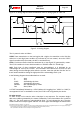
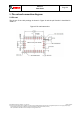
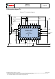
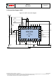
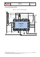
5.3 Connection diagram UART
Figure 10: UART connection diagram
BNO 055
Top View
(Pads not visible!)
2
1
3
4
5
6
7
8
9
10
11
12
13
14
15
19
18
17
16
28
27
26
25
24
23
22
21
20
PIN1
VDDIO
XIN32
XOUT
32
GNDIO
PIN24
PIN23
PIN22
PIN21
COM
0
COM1
COM2
COM3
PIN16
PS0
PIN7
PIN8
CAP
PIN10
nRESET
PIN12
PIN13
INT
PIN15
GND
VDD
PS1
100nF
Optional
OSC input
Optional
OSC input
120nF
TX
6.8nF
RX
INT
nBOOT_LOAD_PIN
100nF
(GNDIO
)
VDDVDDIO
nRESET
Optional
10kΩ
Pull-up
10kΩ
BL_IND