
Data Sheet

BNO055
Data sheet
Page 91
BST-BNO055-DS000-14 | Revision 1.4 | June 2016 Bosch Sensortec
© Bosch Sensortec GmbH reserves all rights even in the event of industrial property rights. We reserve all rights of disposal such as copying and passing on
to third parties. BOSCH and the symbol are registered trademarks of Robert Bosch GmbH, Germany.
Note: Specifications within this document are subject to change without notice.
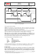
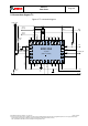
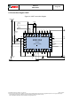
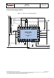
4.6 I2C Protocol
The I²C bus uses SCL (= SCx pin, serial clock) and SDA (= SDx pin, serial data input and
output) signal lines. Both lines are connected to V
DDIO
externally via pull-up resistors so that
they are pulled high when the bus is free.
The I²C interface of the BNO055 is compatible with the I²C Specification UM10204 Rev. 03
(19 June 2007), available at http://www.nxp.com. The BNO055 supports I²C standard mode
and fast mode, only 7-bit address mode is supported. The BNO055 I²C interface uses clock
stretching.
The default I²C address of the BNO055 device is 0101001b (0x29). The alternative address
0101000b (0x28), in I2C mode the input pin COM3 can be used to select between the
primary and alternative I2C address as shown in Table 4-7.
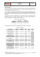
Table 4-7: I2C address selection
I2C
configuration
COM3_state
I2C address
Slave
HIGH
0x29
Slave
LOW
0x28
HID-I2C
X
0x40
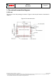
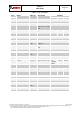
The timing specification for I²C of the BNO055 is given in Table 4-8: I²C timings:
Table 4-8: I²C timings
Parameter
Symbol
Condition
Min
Max
Units
Clock Frequency
f
SCL
400
kHz
SCL Low Period
t
LOW
1.3
s
SCL High Period
t
HIGH
0.6
SDA Setup Time
t
SUDAT
0.1
SDA Hold Time
t
HDDAT
0.0
Setup Time for a
repeated Start Condition
t
SUSTA
0.6
Hold Time for a Start
Condition
t
HDSTA
0.6
Setup Time for a Stop
Condition
t
SUSTO
0.6
Time before a new
Transmission can start
t
BUF
1.3
Idle time between write
accesses, normal mode,
standby mode, low-
power mode 2
t
IDLE_wacc_nm
2
µs
Idle time between write
accesses, suspend
mode, low-power mode
1
t
IDLE_wacc_su
m
450
µs