
Data Sheet


BNO055
Data sheet
Page 90
BST-BNO055-DS000-14 | Revision 1.4 | June 2016 Bosch Sensortec
© Bosch Sensortec GmbH reserves all rights even in the event of industrial property rights. We reserve all rights of disposal such as copying and passing on
to third parties. BOSCH and the symbol are registered trademarks of Robert Bosch GmbH, Germany.
Note: Specifications within this document are subject to change without notice.
4.5 Digital Interface
The BNO055 supports two digital interfaces for communication between the salve and host
device: I
2
C which supports the HID-I2C protocol and I2C Standard and Fast modes; and the
UART interface.
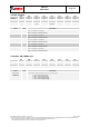
The active interface is selected by the state of the protocol select pins (PS1 and PS0), Table
4-4 shows the mapping between the protocol select pins and the selected interface mode.
Table 4-4: protocol select pin mapping
PS1
PS0
Functionality
0
0
Standard/Fast I2C Interface
0
1
HID over I2C
1
0
UART Interface
1
1
Reserved
It is not allowed to keep the protocol select pins floating.
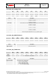
Both digital interfaces share partially the same pins, the pin mapping for each interface is
shown in Table 4-5.
Table 4-5: Mapping of digital interface pins
PIN
I2C Interfaces
(PS1=0b0)
UART Interface
(PS1.PS0=0b10)
COM0
SDA
Tx
COM1
SCL
Rx
COM2
GNDIO
COM3
I2C address select
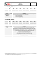
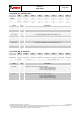
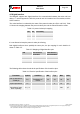
The following table shows the electrical specifications of the interface pins:
Table 4-6: Electrical specification of the interface pins
Parameter
Symbol
Condition
Min
Typ
Max
Units
Pull-up Resistance,
COM3 pin
R
up
Internal Pull-up
Resistance to
VDDIO
20
40
60
k
Input Capacitance
C
in
5
10
pF
I²C Bus Load
Capacitance (max.
drive capability)
C
I2C_Load
400
pF