
Data Sheet


BNO055
Data sheet
Page 46
BST-BNO055-DS000-14 | Revision 1.4 | June 2016 Bosch Sensortec
© Bosch Sensortec GmbH reserves all rights even in the event of industrial property rights. We reserve all rights of disposal such as copying and passing on
to third parties. BOSCH and the symbol are registered trademarks of Robert Bosch GmbH, Germany.
Note: Specifications within this document are subject to change without notice.
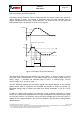
3.8.2.6 Enabling (disabling) for each axis
Any-motion detection can be enabled (disabled) for each axis separately by writing ´1´ (´0´)
to bits AM_X_AXIS, AM_Y_AXIS, AM_Z_AXIS in the GYR_INT_SETTING register. The
criteria for any-motion detection are fulfilled and the Any-Motion interrupt is generated if the
slope of any of the enabled axes exceeds the threshold GYR_AM_THRES for [Slope
Samples+1]*4 consecutive times. As soon as the slopes of all enabled axes fall or stay below
this threshold for [Slope Samples +1]*4 consecutive times the interrupt is cleared unless
interrupt signal is latched.
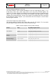
3.8.2.7 Axis of slope / any motion interrupt
The interrupt status is stored in bit GYRO_AM in the INT_EN register. The Any-motion
interrupt supplies additional information about the detected slope.
Table 3-44: Axis selection and any motion interrupt
Params
Value
[Reg Addr]: Register Value
Axis selection
X-axis
[GYR_INT_SETING]: xxxxxxx1b
Y-axis
[GYR_INT_SETING]: xxxxxx1xb
Z-axis
[GYR_INT_SETING]: xxxxx1xxb
Any Motion Filter
settings
Filtered
[GYR_INT_SETING]: x0xxxxxxb
Unfiltered
[GYR_INT_SETING]: x1xxxxxxb
Interrupt Settings
Threshold
[GYR_AM_THRES]: bit6 : bit0
Slope Samples
[GYR_AM_SET]: bit1 : bit0
Awake Duration
[GYR_AM_SET]: bit3 : bit2