
Data Sheet


BNO055
Data sheet
Page 45
BST-BNO055-DS000-14 | Revision 1.4 | June 2016 Bosch Sensortec
© Bosch Sensortec GmbH reserves all rights even in the event of industrial property rights. We reserve all rights of disposal such as copying and passing on
to third parties. BOSCH and the symbol are registered trademarks of Robert Bosch GmbH, Germany.
Note: Specifications within this document are subject to change without notice.
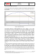
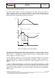
3.8.2.5 Gyroscope Any Motion Interrupt
Any-motion (slope) detection uses the slope between successive angular rate signals to
detect changes in motion. An interrupt is generated when the slope (absolute value of
angular rate difference) exceeds a preset threshold. It is cleared as soon as the slope falls
below the threshold. The principle is made clear in Figure 4.
Figure 4: Principle of any-motion detection
The threshold is defined through register GYR_AM_THRES. In terms of scaling 1 LSB of
GYR_AM_THRES corresponds to 1 °/s in 2000°/s-range (0.5°/s in 1000°/s-range, 0.25°/s in
500°/s -range …). Therefore the maximum value is 125°/s in 2000°/s-range (62.5°/s
1000°/s-range, 31.25 in 500°/s -range …).
The time difference between the successive angular rate signals depends on the selected
update rate(fs) which is coupled to the bandwidth and equates to 1/(4*fs) (t=1/(4*fs)). For
bandwidth settings with an update rate higher than 400Hz (bandwidth =0,1,2) fs is set to
400Hz.
In order to suppress false triggers, the interrupt is only generated (cleared) if a certain
number N of consecutive slope data points is larger (smaller) than the slope threshold given
by GYR_AM_THRES. This number is set by the Slope Samples bits in the GYR_AM_SET
register. It is N = [Slope Samples + 1]*4. N is set in samples. Thus the time is scaling with the
update rate (fs).
slope_th
INT
slope
angular rate
rate(t
0
)
rate(t
0
−1/(4*fs))
slope(t
0
)=gyro(t
0
)−gyro(t
0
−1/(2*bw))
time
time
time
slope_dur
slope_dur