
Data Sheet


BNO055
Data sheet
Page 38
BST-BNO055-DS000-14 | Revision 1.4 | June 2016 Bosch Sensortec
© Bosch Sensortec GmbH reserves all rights even in the event of industrial property rights. We reserve all rights of disposal such as copying and passing on
to third parties. BOSCH and the symbol are registered trademarks of Robert Bosch GmbH, Germany.
Note: Specifications within this document are subject to change without notice.
3.8 Interrupts
3.8.1 Interrupt Pin
INT is configured as interrupt pin for signaling an interrupt to the host. The interrupt trigger is
configured as raising edge and is latched on to the INT pin. Once an interrupt occurs, the INT
pin is set to high and will remain high until it is reset by host. This can be done by setting
RST_INT in SYS_TRIGGER register.
Interrupts can be enabled by setting the corresponding bit in the interrupt enable register
(INT_EN) and disabled when it is cleared.
Interrupt Pin Masking
Interrupts can be routed to the INT pin by setting the corresponding interrupt bit in the
INT_MSK register.
Interrupt Status
Interrupt occurrences are stored in the interrupt status register (INT_STA). All bits in this
register are cleared on read.
3.8.2 Interrupt Settings
3.8.2.1 Accelerometer Slow/No Motion Interrupt
The slow-motion/no-motion interrupt engine can be configured in two modes.
Slow-motion Interrupt is triggered when the measured slope of at least one enabled axis
exceeds the programmable slope threshold for a programmable number of samples. Hence
the engine behaves similar to the any-motion interrupt, but with a different set of parameters.
In order to suppress false triggers, the interrupt is only generated (cleared) if a certain
number N of consecutive slope data points is larger (smaller) than the slope threshold given
by slo_no_mot_dur<1:0>. The number is N = slo_no_mot_dur<1:0> + 1.
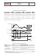
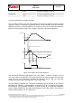
In no-motion mode an interrupt is generated if the slope on all selected axes remains smaller
than a programmable threshold for a programmable delay time. Figure 11 shows the timing
diagram for the no-motion interrupt. The scaling of the threshold value is identical to that of
the slow-motion interrupt. However, in no-motion mode register slo_no_mot_dur defines the
delay time before the no-motion interrupt is triggered.
Table 3-39 lists the delay times adjustable with register slo_no_mot_dur. The timer tick
period is 1 second. Hence using short delay times can result in considerable timing
uncertainty.
If bit SM/NM is set to ‘1’ (‘0’), the no-motion/slow-motion interrupt engine is configured in the
no-motion (slow-motion) mode. Common to both modes, the engine monitors the slopes of
the axes that have been enabled with bits AM/NM_X_AXIS, AM/NM_Y_AXIS, and
AM/NM_Z_AXIS for the x-axis, y-axis and z-axis, respectively. The measured slope values
are continuously compared against the threshold value defined in register ACC_NM_THRES.
The scaling is such that 1 LSB of ACC_NM_THRES corresponds to 3.91 mg in 2g-range
(7.81 mg in 4g-range, 15.6 mg in 8g-range and 31.3 mg in 16g-range). Therefore the
maximum value is 996 mg in 2g-range (1.99g in 4g-range, 3.98g in 8g-range and 7.97g in
16g-range). The time difference between the successive acceleration samples depends on
the selected bandwidth and equates to 1/(2 * bw).