
Data Sheet


BNO055
Data sheet
Page 33
BST-BNO055-DS000-14 | Revision 1.4 | June 2016 Bosch Sensortec
© Bosch Sensortec GmbH reserves all rights even in the event of industrial property rights. We reserve all rights of disposal such as copying and passing on
to third parties. BOSCH and the symbol are registered trademarks of Robert Bosch GmbH, Germany.
Note: Specifications within this document are subject to change without notice.
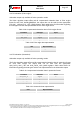
Table 3-21: Gyroscope range settings
Gyroscope dps range
Maximum Offset range in LSB
2000
+/- 32000
1000
+/- 16000
500
+/- 8000
250
+/- 4000
125
+/- 2000
Table 3-22: Gyroscope unit settings
Unit
Representation
Dps
1 Dps = 16 LSB
Rps
1 Rps = 900 LSB
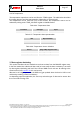
3.6.4.4 Radius
The radius of accelerometer, magnetometer and gyroscope can be configured in the
following registers,
Table 3-23: Radius Default-Reg settings
Reg Name
Default Reg Value (Bit 0 – Bit 7)
ACC_RADIUS_LSB
0x00
ACC_RADIUS_MSB
0x00
MAG_RADIUS_LSB
0x00
MAG_RADIUS_MSB
0x00
There are 4 bytes (2 bytes for each accelerometer and magnetometer) to configure the
radius. Configuration will take place only when user writes to the last byte (i.e.,
ACC_RADIUS_MSB and MAG_RADIUS_MSB). Therefore the last byte must be written
whenever the user wants to changes the configuration. The range of the radius for
accelerometer is +/-1000, magnetometer is +/-960 and Gyroscope is NA.
Table 3-24: Radius range settings
Radius for sensor
Maximum Range
Accelerometer
+/- 1000 LSB
Magnetometer
+/- 960 LSB
3.6.5 Output data registers
3.6.5.1 Acceleration data
In non-fusion mode uncompensated acceleration data for each axis X/Y/Z, can be read from
the appropriate ACC_DATA_<axis>_LSB and ACC_DATA_<axis>_MSB registers.
In fusion mode the fusion algorithm output offset compensated acceleration data for each
axis X/Y/Z, the output data can be read from the appropriate ACC_DATA_<axis>_LSB and
ACC_DATA_<axis>_MSB registers. Refer table below for information regarding the data
types for the acceleration data.