
Data Sheet

BNO055
Data sheet
Page 18
BST-BNO055-DS000-14 | Revision 1.4 | June 2016 Bosch Sensortec
© Bosch Sensortec GmbH reserves all rights even in the event of industrial property rights. We reserve all rights of disposal such as copying and passing on
to third parties. BOSCH and the symbol are registered trademarks of Robert Bosch GmbH, Germany.
Note: Specifications within this document are subject to change without notice.
3. Functional Description
3.1 Architecture
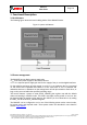
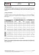
The following figure shows the basic building blocks of the BNO055 device.
Figure 1: system architecture
3.2 Power management
The BNO055 has two distinct power supply pins:
• V
DD
is the main power supply for the internal sensors
• V
DDIO
is a separate power supply pin used for the supply of the µC and the digital interfaces
For the switching sequence of power supply VDD and VDDIO it is mandatory that VDD is powered
on and driven to the specified level before or at the same time as VDDIO is powered ON.
Otherwise there are no limitations on the voltage levels of both pins relative to each other, as
long as they are used within the specified operating range.
The sensor features a power-on reset (POR), initializing the register map with the default
values and starting in CONFIG mode. The POR is executed at every power on and can also
be triggered either by applying a low signal to the nRESET pin for at least 20ns or by setting
the RST_SYS bit in the SYS_TRIGGER register.
The BNO055 can be configured to run in one of the following power modes: normal mode,
low power mode, and suspend mode. These power modes are described in more detail in
section Power Modes