
Instruction Manual


Section 5 - Attachments and Hitches
5-24 31200114
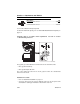
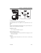
Bale Handler
Description P/N
Tube Bale Handler.......................................................... 0240117
Spike Bale Handler......................................................... 0270118
Use Bale Handler Attachment Capacity Chart
To determine maximum capacity, refer to “Telehandler/Attachment/Fork Capacity” on
page 5-2.
Suspend loads in accordance with requirements set forth in Section
1 - General Safety Practices.
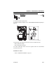
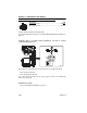
The joystick (1) controls lift/lower movement of the boom and bale handler tilt.
• Move joystick left to tilt up.
• Move joystick right to tilt down.
The rocker switch (2) located on the boom joystick controls the extend/retract
movement of the boom.
Installation Procedure:
•Refer to “Attachment Installation” on page 5-7.
OZ1870
OAH1140
2
1