
User Manual


Bauteile instand setzen
Repair of components
Mise en état des composants
Reparación de componentes
3
English Français Español
© 2002 / 0297 9763
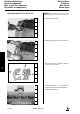
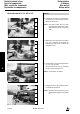
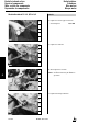
10. Lower turret head by turning the
knurled nut until turning tool
nearly touches the seating surface.
Note: Feed carefully. With a full turn of
the knurled nut (360°) the
turning tool is fed by 1.5 mm.
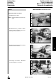
11. Swing tool holder to the inside by
turning the square, until tip of
turning tool is positioned just
before the inner edge of the
seating surface.
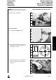
12. Adjust cutting dept by turning the
knurled nut to the right.
Following adjustment, lock refacing
device with setscrew.
Note: Select cutting depth of 0.2 mm.
13. Face seating surface by turning
hand crank evenly.
Note: Only remove so much material
until a perfect seating surface is
reached.
10. Bajar la cabeza giratoria con ayuda
de la tuerca moleteada hasta que
el útil casi tenga contacto con la
superficie de asiento.
Nota: Realizar la aproximación del útil
muy cuidadosamente. Una
vuelta entera de la tuerca
moleteada (360°) corresponde a
un recorrido de aproximación de
1,5 mm.
11. Girando el macho cuadrado,
desplazar el portaútil hacia adentro
hasta que la punta del útil se
encuentre justamente por delante
del canto interior de la superficie
de asiento.
12. Ajustar la profundidad de corte,
girando la tuerca moleteada hacia
la derecha.
Una vez ajustado, afianzar el dis-
positivo de retornear mediante el
tornillo de fijación.
Nota: Elegir una profundidad de
0,2 mm.
13. Girando uniformemente el
manubrio, trabajar la superficie de
asiento hasta que quede plana.
Nota: Quitar sólo tanto material como
sea necesario para obtener una
superficie impecable.
Kurbelgehäuse
Crankcase
Bloc moteur
Bloque motor
10. Baisser la tête porte-outil en
tournant l’écrou moleté jusqu’à ce
que le porte-outil touche presque
le plan de joint.
Nota: avancer avec précaution. A
chaque rotation complète de
l’écrou moleté (360°)
correspond une avance de
1,5 mm.
11. Faire pivoter le porte-outil en
tournant le quatre-pans vers
l’intérieur jusqu’à ce que
la pointe de l’outil de tournage se
trouve juste en face de l’arête
intérieure du plan de joint.
12. Régler la profondeur de coupe en
tournant l’écrou moleté vers la
droite.
Tourner la broche du dispositif de
retification dans le sens horaire et
ainsi rectifier la surface du plan de
joint.
Nota: profondeur de coupe: 0,2 mm
13. Surfacer le plan de joint en
tournant uniformément la poignée
de la manivelle.
Nota: enlever la matière de manière à
avoir un plan de joint en parfait
état.
3.01.04