
Operating instructions

4
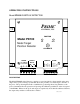
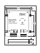
3. Connections to the control circuit of the machine are made through the form C output relay.
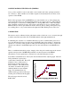
This relay is powered in the OK condition. The relay picture on the front panel of the PD100
indicates the “OK” state. If power is lost to the control the relay is not energized and the
relay defaults to the “OUT” state.
4. Shielded cable from the probe to the board should be run in conduit. The probe is connected
to terminals on the rightmost terminal block labeled Red, White, Black & Shield. Connect
the shield leads (drain wires) from the probe cables to the terminals labeled SHLD. If a splice
is made between the control and probe leave the probe unshielded no more than 20 to 30
mm.
5. The output relay may be operated in a "follower" mode or "memory" mode depending upon
the wiring of the RESET input. The mode connections and definitions are described below.
a) To operate the output in the "follower" mode, jumper RESET and COM. together on the
terminal block. When an OUT condition occurs, the relay drops out and the OUT indicator
comes on. When the target comes within the OK range again, the relay returns to the
normally energized condition, the amber OUT indicator goes out and the green OK indicator
turns on. Automatic reset is normally selected to control the operation when the fault
condition is automatically removed or the PD100 is wired into the stop circuit of a machine
with a manual restart circuit.
b) To operate the output in a "latch" mode, wire the RESET and its associated COM terminal to
the normally open contact of a switch, relay, or controller output. In this mode, when a fault
condition occurs, the relay drops out and the OUT indicator comes on. When the target
comes within range again, the RESET contact must be momentarily activated to bring the
relay back to the OK state.
INPUTS AND CONTROLS
The primary control input to the PD100 is the calibration push-button switch on the front panel.
Use of this switch is described below under CALIBRATION.
The PD100 has two logic inputs labeled CAL and RESET. The CAL input parallels the function
of the calibrate push-button on the front panel allowing the calibration function to be performed
through a remotely located switch wired to this input. The RESET input controls the latching of
the relays as described in item 5 of the Electrical Wiring section above.
The two logic inputs have associated with them two jumper plugs located under the front cover
and immediately behind its associated terminal. The function of these jumpers is described
below under CONFIGURATION SWITCHES AND JUMPERS.
Both the CAL and RESET inputs are ON when low (zero volts) independent of the jumper
settings.