
Operating instructions

2
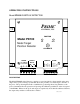
Control Module
The control module allows fast and easy setup and for diagnosis of system errors or problems.
Calibration is achieved through the simple press of a push-button switch. Faults are reported
through different flash patterns on the green and yellow “OK” and “OUT” indicators.
When the unit first powers up, the two indicators flash alternately as the unit determines which
model of probe is attached. If the probe is not recognized, the flash pattern changes with the
yellow indicator on solid and the green indicator flashing. When probe assessment has completed
successfully, the indicators stop flashing
NOTE: When power is first applied to the PD100, there must be no metal near the probe
face to allow for proper probe identification.
Other features of the control module include:
• 95 to 130 or 200 to 250 volt operation selected through internal jumpers.
• Removable terminal blocks for quick change out of the control module.
• Form C relay output providing normally open or normally closed contacts.
• LED indicators report the target position states of OK or OUT.
• Automatic setup of system gain and operating parameters.
• Simple push-button calibration.
• Non-volatile memory that retains all calibration parameters even when power is removed.
• Latching relay output that is cleared by asserting the RESET input.
• Probe fault detection and reporting via the two front panel indicators.
• External Calibrate terminals for convenient placement of the calibrate switch
• Metal present output to indicates metal sensed even if outside the calibration range.
Probes
The PD100 operates with a several different Prime magnetic probes including Models PM4,
PM10, and PM15. All probes are potted and completely sealed. The probes do not respond to
small amounts of fine metal filings, oil or dirt.