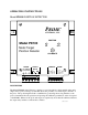
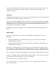
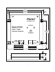
OPERATING INSTRUCTIONS Model PD100 POSITION DETECTOR PRIME CONTROLS, INC. POSITION Model PD100 OK OUT Metal Target Position Detector CALIBRATE SHLD BLACK WHITE PROBE RED CAL RESET CONTROL COM AC AC OUTPUT RELAY METAL POWER SET JUMPERS (120V OR 240V) DESCRIPTION The Model PD100 Position Detector comprises a control module in a sheet metal housing and a single remote probe, forming a system that detects the proximity of a metal target to the face of the probe.
Control Module The control module allows fast and easy setup and for diagnosis of system errors or problems. Calibration is achieved through the simple press of a push-button switch. Faults are reported through different flash patterns on the green and yellow “OK” and “OUT” indicators. When the unit first powers up, the two indicators flash alternately as the unit determines which model of probe is attached.
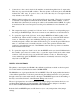
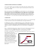
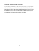
Probe Model PM4 PM10 PM15 Probe Diameter 18 mm (0.070”) 30 mm (1.18”) 36 mm (1.42”) Min Cal Distance 0 mm (0”) 0 mm (0”) 0 mm (0”) Max Cal Distance 0.6 mm (0.024”) 1.5 mm (0.060”) 2.0 mm (0.080”) INSTALLATION Installation of the individual components of the Position Detector system is covered in the following paragraphs: PD100 Control Module The control board is designed to mount on the back panel of an electrical enclosure using the four mounting slots at the edges of the enclosure. The footprint is 6.
3. Connections to the control circuit of the machine are made through the form C output relay. This relay is powered in the OK condition. The relay picture on the front panel of the PD100 indicates the “OK” state. If power is lost to the control the relay is not energized and the relay defaults to the “OUT” state. 4. Shielded cable from the probe to the board should be run in conduit. The probe is connected to terminals on the rightmost terminal block labeled Red, White, Black & Shield.
A two position DIP switch between the two main connectors, is visible from the connector edge of the unit. These switches are for future expansion and currently have not effect on the operation of the unit. OUTPUTS The PD100 outputs include a form C relay for reporting OUT conditions and a dc logic output for reporting no metal within sensing range of the probe. The logic output is labeled METAL since it provides an indication that the metal target is within sensing range.
CONFIGURATION SWITCHES AND JUMPERS A two position switch is located on the main control circuit board in the opening between the two connectors. These switches are for future expansion and currently have not effect on the operation of the PD100. Each of the logic inputs (CAL and RESET) has associated with it a two position jumper plug located under the front cover and immediately behind its associated connector. These jumpers allow the inputs to be driven by a sinking (NPN) or sourcing (PNP) device.
FIRMWARE VERSION From time to time, as improvements are made to Prime products, the firmware controlling the units is revised. When setting a unit up or troubleshooting it may be necessary to determine the version number for the firmware installed in your unit. The version numbers begin with 1.0 and are incremented either by tenths (1.1, 1.2, etc.) for small revisions or by the integer digit (1.0, 2.0, etc.) for more significant revisions.
TROUBLESHOOTING Should trouble develop, proceed as follows: 1. Check AC input power to the control module 2. Check the fuse, accessible at the lower left side of the PD100 housing. 3. When powers is applied, if the green and amber indicators show a response to the metal condition in front of the probe and the output relay does not switch, check that the reset jumper is installed (if you want the relay to follow the metal condition). The jumper is installed between RESET and COM. on the terminal strip.
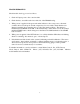
165.1 (6.50) 149.2 (5.875) 7.9 (0.31) PRIME CONTROLS, INC. POSITION Model PD100 OK OUT 101.6 (4.0) 158.8 (6.25) Metal Target Position Detector CALIBRATE 28.6 (1.125) SHLD BLACK WHITE CAL PROBE RED COM RESET CONTROL AC AC OUTPUT RELAY METAL POWER SET JUMPERS (120V OR 240V) 15.2 (0.600) 9 33.5 (1.
LIMITATION AND EXCLUSION OF WARRANTIES All goods purchased from Prime Controls, Inc. shall be free from defects in materials, design and workmanship under normal conditions of use for one year from the date of shipment. THIS WARRANTY IS THE SOLE WARRANTY AND IS EXPRESSLY IN LIEU OF ALL OTHER WARRANTIES, EXPRESSED OR IMPLIED, INCLUDING BUT NOT LIMITED TO ANY IMPLIED WARRANTY OF MERCHANTABILITY OF FITNESS FOR A PARTICULAR PURPOSE.