
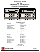
User`s guide


Page 4 P/N 39818D Copyright © 2001 Detection Systems, Inc. DS7080iP-32 Reference Guide
1.0 Specifications
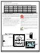
1.1 Enclosure Housing
The standard enclosure is manufactured from 20 Ga., cold-rolled
steel, and measures 12.5 in. Wide, by 14.5 in. High, by 3 in. Deep
(31.8 cm W x 36.8 cm H x 7.6 cm D). A keyed lock is included, and
this enclosure has a provision for an optional tamper switch (required
for Commercial Burglary applications) for monitoring the door.
1.2 Temperature
• Storage and Operating Temperature: +32° to +120°F (0° to +49°C)
1.3 Power
• Input power: 16.5 VAC, 40 VA, 60 Hz.
• Auxiliary regulated power: 11.8 -12.5 VDC, 1.0 A.
(200mA
for UL Listed Systems. 1.0 A
not investigated by UL.)
• Optional Standby battery (P334): 12 V, 7.0 AH
• Control panel current draw: 150 mA
1.3.1 Accessory Power
• DS7443 keypad current draw: 45 mA, Standby & Alarm
• DS7445 keypad current draw: 75 mA, Standby & Alarm
• DS7447 keypad current draw: 100 mA, Standby & Alarm
• DS7488 Octal Relay 10 mA for the module plus 40
mA for each energized relay
• EX8 Expansion Module: 35 mA, Standby & Alarm
The total current for all auxiliary devices, including keypads
and smoke detectors = 1.2 A standby and alarm.
1.4 Outputs
• Alarm Output: Normally Closed, 1.0 Amp contact connected
to auxiliary power. Can be programmed for
steady or pulsed output.
• Programmable Output 1*: Solid state current sink (1 A max.).
(200mA for UL Listed Systems. 1 A
not investigated by UL.)
Can be
used for alarm, arming state, or ac-
cess control.** This output is gen-
erally programmable.
• Programmable Output 2*: Solid state voltage source (500 mA
max.).
(200mA for UL Listed
Systems. 500mA not investigated
by UL.)
This is the smoke power
reset for Zone 1 when it is used as
afire zone for 2-wire smoke
detectors. Can be used for alarm,
armingstate, or access control.**
* = Current draw should be subtracted from either maximum
auxiliary or maximum alarm current draw.
** = Not investigated to the requirements of UL294.
1.5 Zones
• 1 or 2 Partitions. Zones may be assigned to one or both partitions.
Zones assigned to both partitions become common zones.
• 8 zones, plus 1 trouble zone on the main control board. The trouble
zone cannot be assigned to a partition.
• 24 Expansion zones using EX8 Zone Expansion Module. Each
EX8 adds 8 additional zones. Up to three EX8 modules can be
added to the system.
• On Board Zone Response Time: 300 milliseconds.
1.6 Keypads
1.6.1 DS7443 Keypad
• Total number of keypads: 4 Keypads
• Maximum wire length each run: 400 feet (122m)
• Maximum wire length total: 1600 feet (488m) in system
• Wire type: 4 conductor, unshielded, #22 AWG (0.8mm) or 18
AWG (1.0mm) "Telephone quad".
Only one DS7443 is allowed per cable. Each DS7443 must
have a “home run” back to the DS7080iP-32. Do not “daisy
chain” or place two DS7443 keypads on any cable run.
1.6.2 DS7445/DS7447 Keypads
• Total number of keypads: 4 Keypads
• Maximum wire length each run: 1000 feet (305m)
• Maximum wire length total: 4000 feet (1220m) in system
• Wire type: 4 conductor, unshielded, #22 AWG (0.8mm) or 18
AWG (1.0mm) "Telephone quad".
If using #22 AWG (0.8mm) wiring, there can be no more
than two keypads allowed on any 1000 foot (305m) run.
Three keypads are allowed on any 1000 foot (305m) run if
#18 AWG (1.0mm) wire is used. Keypad wiring can be
“daisy-chained” or “home-run,” but the cables can NOT be
shared with other devices (e.g. telephone or siren wiring).
The DS7488 and EX-8 can only be “home-run.”
1.7 Communicator
Will report to two phone numbers with full single, double and back-
up reporting. Communicates in SIA, 3/1, 3/1 Ext., 4/1, 4/2, BFSK,
Contact ID, High Speed 4/9, and Pager formats.
The ringer equivalence is 0.1B
1.8 Users
The system allows up to 24 individual users. Each user will have his
own PIN number (the 4- or 6-digit code entered at the keypads) and
his own authority level (to determine which functions he may
perform).
1.9 Lightning Protection
MOVs and spark gaps provide protection from lightning surges and
static discharges.
1.10 Burglar/Fire Zone Inputs
• Number of circuits 8 Circuits
• End-of-line resistor 2.21k ohms
1.11 Fire Signal Initiating Circuit (2-wire mode)
The Fire circuit (zone 1) will work with 2- or 4-wire detectors. It has
an optional alarm verification.
• Number of 2-wire circuits: 1 circuit, compatibility identifier A
• Type of circuit: Class B, latching
• End-of-Line resistor: 2.21k ohms
• Supervisory current: 5 mA
• Maximum current for alarm: 13 mA
• Maximum short circuit current: 25 mA
• Maximum line resistance: 65 ohms
• Circuit voltage range: 8.5 to 14.0 VDC
• Maximum detectors per zone: 20 detectors (2-wire)
• Total detector standby current: 2.5 mA